- Связываем Arduino и Android через Bluetooth
- Нам понадобится
- Создание приложения для Android
- Заготовка
- Настройка эмулятора
- Заполнение Activity
- Пробный запуск
- Написание кода для Android
- Правка манифеста
- Добавляем основной код
- Написание скетча
- Особенности заливки скетча
- Результат
- Заключение
- Блютуз подключение в Android (проект для Arduino). Часть 1.
- Смотрите видео: Блютуз подключение в Android (проект для Arduino)
- Смотрите видео: Найдена лучшая замена эмулятора Android. (для Android Studio)
- Cкачать архив для ознакомления — проект Блютуз подключение Android и Arduino:
- Смотрите видео: Блютуз подключение в Android (проект для Arduino)
- Android arduino bluetooth android studio
- Android Development
- Install and Setup
- GUI layout
- Checkbox
- RX Read Buffer
- Bluetooth Status
- Bluetooth ON/OFF buttons
- Show Paired Devices button
- Discover Button
- Devices View
- Program Permissions
- Member Variables
- onCreate
- GUI Handler
- Button listeners
- Bluetooth ON and OFF
- Discovering devices
- Listing Paired Devices
- Connecting as a Client
- RX/TX Bluetooth Thread
- Build and Run
- Arduino Code
- Putting it all together
Связываем Arduino и Android через Bluetooth
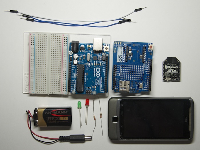
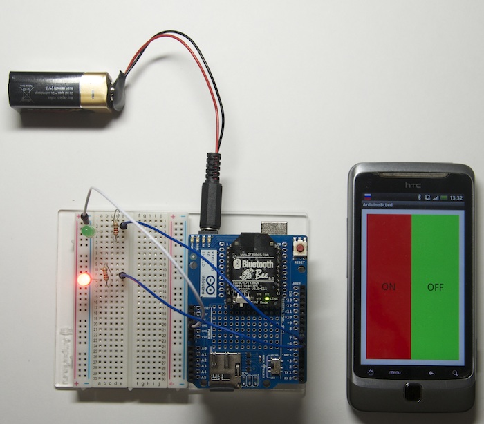
В данной статье будет подробно расписано создание небольшого приложения для мобильной операционной системы Android и скетча для Arduino. На Arduino Uno будет стоять Wireless Shield с Bluetooth-модулем. Приложение будет подключаться к Bluetooth-модулю и посылать некую команду. В свою очередь скетч по этой команде будет зажигать или гасить один из подключенных к Arduino светодиодов.
Нам понадобится
Создание приложения для Android
Заготовка
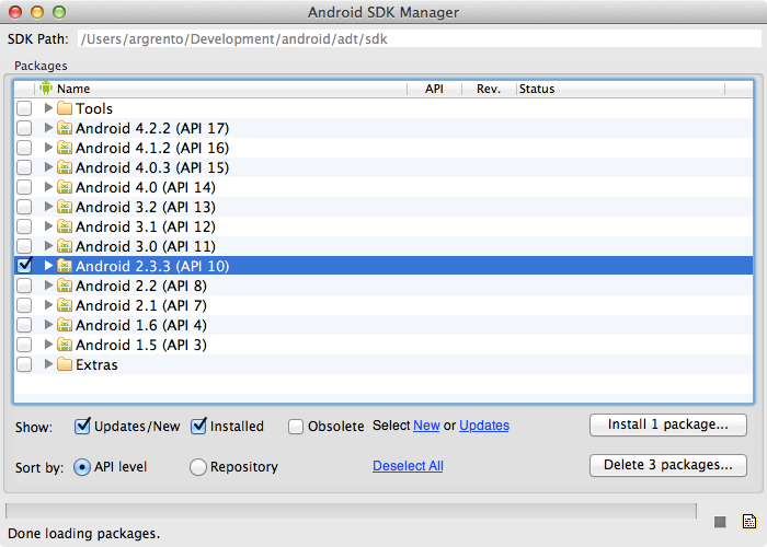
Разработка для ОС Android ведется в среде разработки ADT, Android Development Tools. Которую можно скачать с портала Google для разработчиков. После скачивания и установке ADT, смело его запускаем. Однако, еще рано приступать к разработке приложения. Надо еще скачать Android SDK нужной версии. Для этого необходимо открыть Android SDK Manager «Window → Android SDK Manager». В списке необходимо выбрать нужный нам SDK, в нашем случае Android 2.3.3 (API 10). Если телефона нет, то выбирайте 2.3.3 или выше; а если есть — версию, совпадающую с версией ОС телефона. Затем нажимаем на кнопку «Install Packages», чтобы запустить процесс установки.
После завершения скачивания и установки мы начинаем создавать приложение. Выбираем «File → New → Android Application Project». Заполним содержимое окна так, как показано на рисунке.
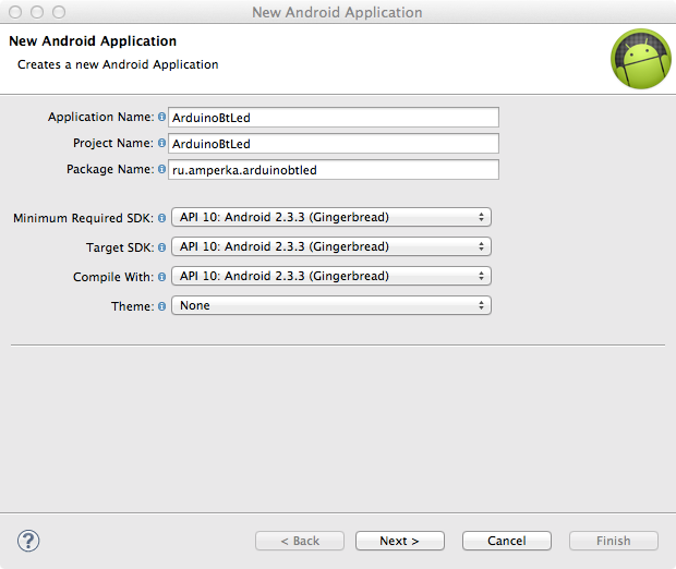
В выпадающих списках «Minimum Required SDK», «Target SDK», «Compile With» выбираем ту версию, которую мы скачали ранее. Более новые версии SDK поддерживают графические темы для приложений, а старые нет. Поэтому в поле «Theme» выбираем «None». Нажимаем «Next».
Снимаем галочку с «Create custom launcher icon»: в рамках данной статьи не будем заострять внимание на создании иконки приложения. Нажимаем «Next».
В появившемся окне можно выбрать вид «Activity»: вид того, что будет на экране, когда будет запущено приложение. Выбираем «Blank activity», что означает, что мы хотим начать всё с чистого листа. Нажимаем «Next».
В нашем приложении будет всего одно Activity, поэтому в появившемся окне можно ничего не менять. Поэтому просто жмем на «Finish».
Все, наше приложение создано.
Настройка эмулятора
Отладка приложений для Android производится на реальном устройстве или, если такового нет, то на эмуляторе. Сконфигурируем свой.
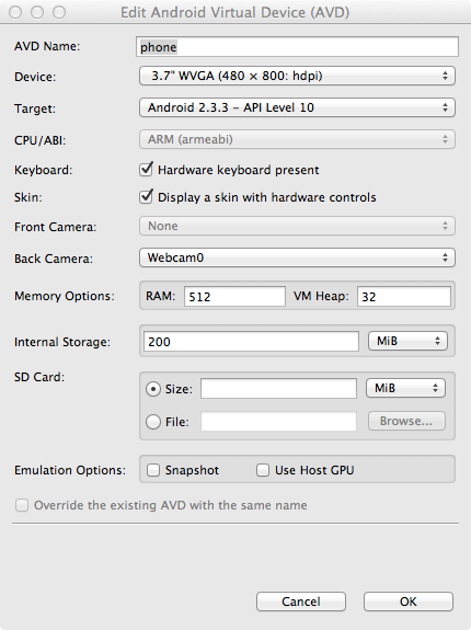
Для этого запустим «Window → Android Virtual Device Manager». В появившемся окне нажмем «New». Заполняем поля появившейся формы. От них зависит сколько и каких ресурсов будет предоставлять эмулятор «телефону». Выберите разумные значения и нажимайте «ОК».
В окне Android Virtual Device Manager нажимаем кнопку «Start». Это запустит эмулятор. Запуск занимает несколько минут. Так что наберитесь терпения.
В результате вы увидите окно эмулятора подобное этому:

Заполнение Activity
Activity — это то, что отображается на экране телефона после запуска приложения. На нем у нас будет две кнопки «Зажечь красный светодиод» и «Зажечь синий светодиод». Добавим их. В панели «Package Explorer» открываем res/layout/activity_main.xml . Его вид будет примерно таким же, как на скриншоте.

Перетаскиваем 2 кнопки «ToggleButton» на экранную форму. Переключаемся во вкладку «activity_main.xml» и видим следующий код:
Это ни что иное, как наша Activity, которая отображается не в виде графики, а описанная в формате XML.
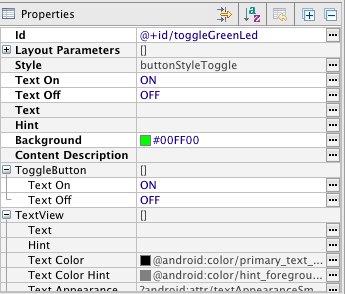
Сделаем имена компонентов более понятными. Изменим поля android:id следующим образом.
А еще добавим им подписи, изменим их цвет и размер текста. Результирующий код разметки будет выглядеть следующим образом.
Эти же изменения можно сделать и в графическом режиме, воспользовавшись вкладкой «Outline/Properties».
Пробный запуск
Мы можем запустить только что созданное приложение на эмуляторе. Идем в настройки запуска «Run» → Run Configurations», в левой части нажимаем на «Android Application». Появляется новая конфигурация «New_configuration». В правой части окна выбираем вкладку «Target» и выбираем опцию «Launch on all compatible devices/AVD».

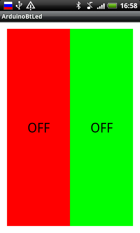
Нажимаем «Apply», а затем «Run». Приложение запустится в эмуляторе.

Можно понажимать кнопки. Но ничего происходить не будет, поскольку обработчики нажатий еще нами не написаны.
Чтобы запустить приложение на реальном устройстве, необходимо включить в его настройках опцию «Отладка USB» и подключить его к компьютеру.
На реальном устройстве приложение выглядит абсолютно аналогично.
Написание кода для Android
Правка манифеста
Каждое Android-приложение должно сообщить системе о том, какие права необходимо ему предоставить. Перечисление прав идет в так называемом файле манифеста AndroidManifest.xml . В нем мы должны указать тот факт, что хотим использовать Bluetooth в своем приложении. Для этого достаточно добавить буквально пару строк:
Добавляем основной код
Пришла пора вдохнуть жизнь в наше приложение. Открываем файл MainActivity.java (src → ru.amperka.arduinobtled). Изначально он содержит следующий код:
Дополним код в соответствии с тем, что нам нужно:
Передавать на Arduino мы будем один байт с двузначным числом. Первая цифра числа — номер пина, к которому подключен тот или иной светодиод, вторая — состояние светодиода: 1 — включен, 0 — выключен.
Число-команда, рассчитывается очень просто: Если нажата красная кнопка, то берется число 60 (для красного светодиода мы выбрали 6-й пин Arduino) и к нему прибавляется 1 или 0 в зависимости от того, должен ли сейчас гореть светодиод или нет. Для зеленой кнопки всё аналогично, только вместо 60 берется 70 (поскольку зеленый светодиод подключен к 7 пину). В итоге, в нашем случае, возможны 4 команды: 60, 61, 70, 71.
Напишем код, который реализует всё сказанное.
Написание скетча
Данные, которые принимает Bluetooth-модуль, приходят через UART (он же Serial-соединение) на скорости 9600 бит/с. Настраивать Bluetooth-модуль нет никакой необходимости: он сразу готов к работе. Поэтому скетч должен уметь следующее:
Особенности заливки скетча
Для связи Bluetooth-Bee с контроллером используются те же пины (0 и 1), что и для прошивки. Поэтому при программировании контроллера переключатель «SERIAL SELECT» на «Wireless Shield» должен быть установлен в положение «USB», а после прошивки его надо вернуть в положение «MICRO».
Результат
Заключение
В данной статье мы научились создавать приложения для операционной системы Android и передавать данные по Bluetooth. Теперь при нажатии на кнопку на экране телефона на базе операционной системы Android, произойдет изменение состояния светодиода на плате.
Вы можете развить мысль и сделать более дружественный интерфейс на Android, управлять с его помощью гораздо более сложными устройствами, публиковать классные приложения в Android Market и ещё много-много всего интересного!
Источник
Блютуз подключение в Android (проект для Arduino). Часть 1.
Всем привет, сегодня я хотел бы показать вам, как написать приложение для Android, которое будет использовать Bluetooth для подключения к Arduino.
Смотрите видео: Блютуз подключение в Android (проект для Arduino)
В частности, это в рамках моего проекта связи Android устройства с Arduino, поскольку меня недавно с АлиЭкспресс пришел модуль hc-06, это модуль Bluetooth для подключения.
Давайте напишем небольшой проект, большой небольшой, ну посмотрим, и в середине, когда дойдём до графической части написания layout для приложения, я вам покажу интересный эмулятор который я думаю вас заинтересует и решит Ваши проблемы с производительностью.
Давайте создадим новый проект, это как обычно EmptyActivity , дадим названием, допустим Bt-hc-06 , да будет так.
Делаем под минимальную, под пятую версию, там разберемся.
Завершилось создание проекта, давайте перейдём в наш проект в манифест, нам нужно будет добавить строки для разрешение работы с блютузом.
Обратите внимание, в примерах кода для AndroidManifest.xml и activity_main.xml после угловой скобки я добавил пробел, чтобы на сайте теги разметки не перемешались с тегами самой статьи. В своем коде , , , , и т.д., а так же закрывающие теги пишите слитно.
Будет 2 строки в 2 разрешения Bluetooth и Bluetooth_ADMIN также давайте сделаем чтобы наша MainActivity располагалась в портретном виде.
Манифест больше нам не понадобится перейдём в ActivityMain.xml в слой LayOut, поскольку код у меня уже в принципе набран, сверстан, я буду лишь добавлять блоками фрагменты кода и буду где-то походу пояснять, так сказать, что у нас к чему и зачем.
Закрываем RelativeLayout это будет у нас общая так сказать рамка, канва.
Добавляем textview с Id textinfo , добавим listview , список куда у нас будут подгружаться данные об найденных устройствах, далее мы добавим FrameLayout , он будет нужен для отображение всех устройств, которые мы будем видеть, к которым вернее мы подключимся.
Также во внутрь FrameLayout мы добавим RelativerLayout для позиционирования элементов внутри.
Я хочу показать вам на примере четырех канального включателя-выключателя, который будет подключаться к Bluetooth адаптеру и передавать команды, которые Arduino будет принимать и соответственно на этих 4 пинах Arduino будет выполняться какие-либо действия.
Это может быть, как включение реле, как мигание светодиодов, различное, то есть мы конкретно здесь в коде и не прописываем, что мы на самом деле будем подключать в Arduino, но в принципе у нас будет кнопка 1, кнопка 2, кнопка 3, кнопка 4, типа ToggleButton, которая фиксирует нажатое состояние.
С RelativeLayout мы практически закончили, давайте теперь перейдем в дизайн, и обратите внимание, в виде компонентов получается следующая картина: надпись, список, и вот это вся панель.
На данный момент кнопки у нас не видны, когда мы выберем какой-то пункт из списка сопряженных устройств, а это будет наша Arduino с Bluetooth модулем, то мы должны будем увидеть список с кнопками.
Давайте мы переключим listView , мы его сделаем невидимым,
а для FrameLayout напишем
сделав его видимым, сохраним, и вот у нас просто будут располагаться кнопки.
Эти кнопки типа ToggleButton , при нажатии на которые они фиксируют, свое состояние, при повторном нажатии, естественно меняется цвет, меняются названия.
По поводу кнопок, я хотел вам показать, как у меня проставлены названия кнопок, здесь событии нажатия свойство textOff примет значение название кнопки + OFF, при повторном нажатии textOn примет значение название кнопки + ON, кнопки я называл по номеру используемых пинов в ардуинке.
Всё здесь позиционировано, отступы по 70 единиц от краев, и 48 друг от друга, поскольку то устройство на котором будут тестировать немножко не совпадает по размерам и скорей всего съедет в сторону…)
Давайте теперь посмотрим, что у нас получилось по поводу эмулятора, я хочу вам представить очень удобный, на мой взгляд, эмулятор называется LDPlayer (не путать с ЛДПР)…)
Смотрите видео: Найдена лучшая замена эмулятора Android. (для Android Studio)
Так же дополнительная информация есть в основном видео к этой статье. А в двух словах — стоит попробовать!
Переключим обратно значения видимости для ListView и FrameLayout с кнопками: скроем как это было и вернёмся всё-таки к написанию кода.
Список у нас пока пустой, собственно тут есть кнопки, но они будут скрыты, пока не произойдет соединение по блютуз и никакие данные в него не передаются.
Займемся теперь самой большой частью кода, скопируйте весь текст MainActivity.java, изменив только имя пакета, если оно отличается от моего.
Поясню идею в целом: при соединении телефона с блютуз модулем станут видны кнопки, при нажатии на них будет меняться их состояние, вид, текст. Функция Toast будет писать, какая кнопка нажата и по блютуз будут передаваться команды – буква a – (английская, маленькая)- нажата кнопка D10 – включить, на выход Arduino 10 десятый идет напряжение. Буква A — (английская, большая)- повторно кнопка D10, выключить, на выход Arduino десятый пин напряжение перестает подаваться.
То же самое правило действует и для остальных кнопок: D11 , D12 , D13 , — b/B, c/C, d/D – вкл/выкл.
Статью со скетчем для Arduino выложу в ближайшее время, так что посещайте сайт чаще, добавляйтесь в группы в Одноклассниках, вКонтакте, или на facebook, в них я всегда публикую анонсы новых статей. Подписывайтесь на канал в ютубе, чтобы не пропустить выход видео, исходники проекта вы можете скачать по ссылке ниже.
Cкачать архив для ознакомления — проект Блютуз подключение Android и Arduino:
Смотрите видео: Блютуз подключение в Android (проект для Arduino)
Источник
Android arduino bluetooth android studio
This article will detail how to make a simple bluetooth application using Android Studio and demo it using an Arduino to toggle an LED and send data back-and-forth. No prior knowledge of Android development is needed, however it will help to know some basics of Java programming. I will be using an Android phone for testing purposes and not an Android virtual device. The Android app that you develop can be used with any other microcontroller, I only used the Arduino in this example with the HC-06 bluetooth module since they are both cheap and popular. I’m going to be creating other posts with different microcontrollers that use this same phone app. Some of the funtionality that I will be using was taken from the offical bluetooth SDK doc. I also derived some ideas from this blog post.
Android Development
Install and Setup
If you haven’t already, download and install the Android IDE and SDK.
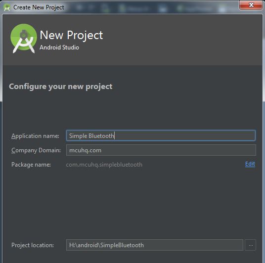
- Create a new project by navigating to «File->New Project»
- I named my project «Simple Bluetooth» and my company domain as «mcuhq.com».

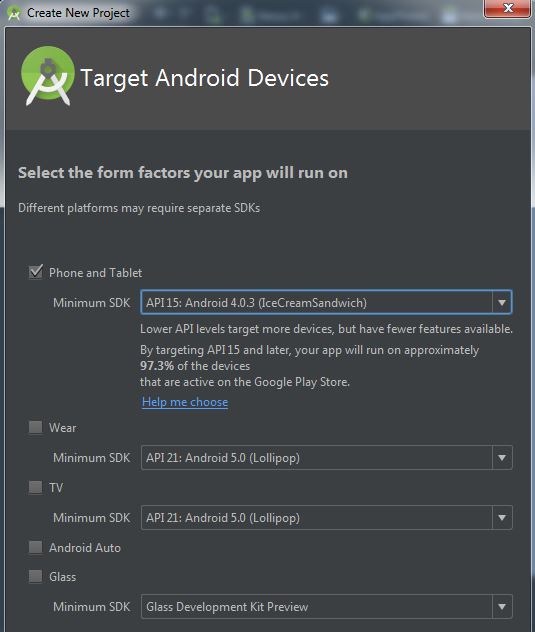
- The minimum API version was auto-selected to be at 15 for me at the time of writting which covers 97.3% of all devices on the market (pretty good coverage I’d say). Leave all of the other checkboxs blank since we won’t be needing them.
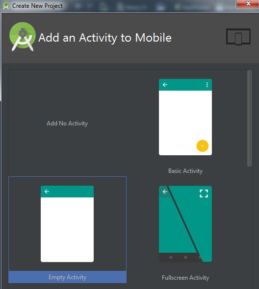
- Select the «Empty Activity»
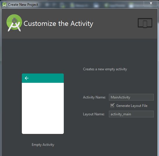
- Keep the Activity Name default as MainActivity .
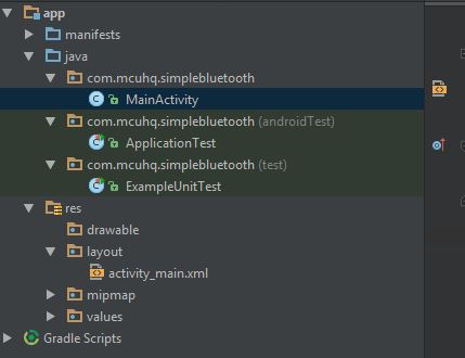
- Your project will now be created. It should look something like this:
GUI layout
I will be making the GUI layout first since it is easier to grasp what we are trying to do via the visual elements. The GUI builder has similarities such as anchors and layout managers similar to Java Swing. We will be using the LinearLayout (Vertical) to make our application. Without a layout manager, your GUI components would arrange themselves differently depending on the screen size of the device. The default layout choice is the RelativeLayout and works by aligning all of the components in relation to the first component placed on the screen (or as dictated by you). You can see this effect by opening activity_main.xml found in your app/res/layout folder structure and dragging a text component onto the screen. Notice how a green line indicates its anchor relationship.
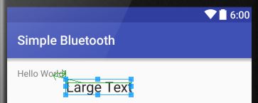
Moving the default Hello World! text will now move the text that you just placed. Making an app using this RelativeLayout is straightforward and easy, but often causes headaches with larger or smaller screens than the one you are developing on.
Drag the LinearLayout (Vertical) from the Palette to the component tree. Then drag a checkbox from the Palette to your main activity screen and double-click on it to call it «Toggle LED». Align it in the middle of the screen. This checkbox will be used to turn ON and OFF an LED on the Arduino. Your Component screen should now look like th 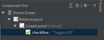
This next portion will be easier to accomplish and convey by just editing the markup XML from the designer. You can view this by clicking on the lower-left hand side of the viewport where it says «Text»
Paste this entire text into your activity_main.xml .
If your activity or project name differs from mine, you may need to adjust the tools:context value in the XML to match your settings. This should be highlighted in red inside the IDE
Flip back to the designer and you should see the following:
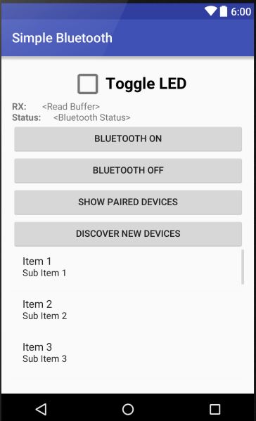
Lets go over what every function does and how we were able to make the GUI look like it does:
Checkbox
Nothing difficult here, but note how I used scaleX and scaleY to make this appear larger than the default size
RX Read Buffer
Here is where the data that we receive from the Arduino will be displayed. The demo code on the Arduino will be simply incrementing a 32-bit counter variable.
Note that I used a horizontal linear layout for two textviews. This was inspired by this SO post. These two textviews will be on the same line, side-by-side, and fill the horizontal width of your phone. The RX: label will fill 10% of the width with the rest going to be displaying the received data.
Bluetooth Status
This horizontal line contains the status of the bluetooth radio on your phone. It will indicate if its on, off, connecting to a device, or if a connection failed. The code is formated exactly as above the RX Read Buffer.
Bluetooth ON/OFF buttons
These buttons will turn the Bluetooth radio ON or OFF
Show Paired Devices button
This will populate the list with devices that your phone already has paired in the past
Discover Button
Pressing this button will place your bluetooth module in discovery mode while it seeks out devices it can pair to.
Devices View
This scroll box is called a ListView and will contain the devices that were previously paired or are currently being discovered.
That’s it for the GUI side of things. Now we are going to write Java to interact with our components. Please note that the code be referencing the GUI via each component’s ID.
Program Permissions
You should have probably noticed by now that downloading certain apps onto your phone will display their requirements such as being able to access your contacts, email client, etc. We need to do the same thing to our app and tell the user that this application will require access to the bluetooth module. Open your AndroidManifest.xml file and paste the following in the root of the manifest node.
For Android 6.0 and above, I had to include the location permission in order to be able to scan for bluetooth devices.
I made the entire program in one class called MainActivity for simplicity. In future programs, it is probably good practice to separate the logic such as bluetooth discovery and application code into their own activity file. For now I merged them all into one.
For the impatient, You can paste the following code into your MainActivity.java file. You may need to change the package name and such if you did not use my default settings as above. I will attempt to explain what the code does as well.
All of my class variables are prefaced with an m character used to designate that it is a class member.
Member Variables
We will be grabbing a reference to the GUI components to listen to their onClick events and to update their text values throughout our class. I made them all class members so they can be referenced anywhere inside the class without needing to get the reference multiple times.
A Handler type is also created so that our application can communicate back with the main running thread with updates such as bluetooth status and any received data from our Arduino. Each application will have a main thread typicalled called the «GUI» thread in which all updates to your screen are performed. You don’t want to push to much work to this thread or poll for an event (called «blocking») because then your screen will become unresponsive. You can read more about this here.
We will create a handler that receives data from our background threads and updates our GUI components. A separate background worker thread called mConnectedThread will be used to receive and send data to our bluetooth device. This thread will NOT run on our main thread and so it can block and handle large amount of requests without creating a sluggish effect on our GUI. Our threads can pass data to one another, however they need to know what the data type is so it can be casted appropriately. Simply use some constants to identify these.
Finally, the mBTSocket is the data path layer needed to send and receive data as a client to our HC-06 device.
onCreate
Every activity has an onCreate method that gets called. We will «override» the default functionality and place in our own. First, we gather our components, selecting them via their IDs from the GUI. We cast them to the type we expect.
The following creates a listView to contain our bluetooth devices. An ArrayAdapter is set onto the listView so that all items in this array will reflect on the GUI. You can think of this as setting the model to the view with the model being the arrayAdapter and the view being the listView . The BluetoothAdapter class variable represents the local device Bluetooth adapter that will be used for bluetooth tasks such as discovery and connection.
GUI Handler
This function will be called from our bluetooth ConnectedThread thread and another thread that handles the discovery stage. Recall that all GUI updates should be performed in the GUI thread.
Button listeners
A quick check will be made to ensure that your phone has bluetooth capability. If it does, then actions are assigned to each button’s click event. The
Bluetooth ON and OFF
The Toast class provides an easy way to display quick notifications in Android. The following code is pretty straight forward. The android bluetooth docs cover the basics on turning ON/OFF and discover of bluetooth devices
A fine detail happens when you enable the bluetooth radio. The application must «listen» to the dialog box that is shown to the user. If the users clicks «no», we don’t want to show the status that bluetooth is enabled. We use an Activity for this reason. As quoted from the Android bluetooth documentation:
«The REQUEST_ENABLE_BT constant passed to startActivityForResult() is a locally defined integer (which must be greater than 0), that the system passes back to you in your onActivityResult() implementation as the requestCode parameter. If enabling Bluetooth succeeds, your activity receives the RESULT_OK result code in the onActivityResult() callback. If Bluetooth was not enabled due to an error (or the user responded «No») then the result code is RESULT_CANCELED.»
Discovering devices
During discovery, we will register a «listener» class that will update our listView by adding items to its model (the mBTArrayAdapter ) once a notification is made that a bluetooth device was found.
registerReceiver(blReceiver, new IntentFilter(BluetoothDevice.ACTION_FOUND));
The rest of the code was lifted from the offical Android example code found here
Listing Paired Devices
This function uses some of the built-in functionality of our mBTAdapter in getting the already paired bluetooth devices.
Connecting as a Client
We will need to open a data pipe, or socket, to our bluetooth device that is connected to the Arduino. We can do this by opening up a socket once we know its address. This functionality will happen once a device is «clicked» on your listView . Note that we don’t want this time-consuming process to happen on the GUI thread as discussed previously, so lets use a background thread to open the socket and display its status to our GUI via the Handler function created above.
The address and name of the device is retried from the listView . A new thread is created and an attempt is made to open the socket. If the call returns with IOException , update our GUI saying it failed. Else, continue and try to make a connection. If that fails, also report the error to our GUI status label. If all succeeds, create a new thread, mConnectedThread and pass it our socket connection to monitor our RX/TX tasks.
Note how we are sending data asynchronously back to our GUI thread via the mHandler instance. We can pass a series of integers and an object — in our case a string for the status label to update.
RX/TX Bluetooth Thread
This background worker thread example is slightly modified from the Android Docs. The most significant addition is a small delay of 100ms when receiving data. SystemClock.sleep(100); . I placed this delay in so that we will collect all of the data before posting to the main thread. Without a delay, the GUI would update after every byte received instead of the whole perceived payload. Our example is just reading a uint32 variable of 4 bytes. A more advanced routine may want to wait until a CRC is matched or special terminating character recieved such as a newline «\n».
Build and Run
Click the compile button to see if everything compiles. You will need to enable USB debugging on your phone in the developer options in order to directly run code on your phone. Test to verify that you can turn on the bluetooth radio, scan for devices, and view your previously paired devices.
Arduino Code
I’ve constructed a simple sketch that increments a 32-bit variable and sends it to the HC-06 bluetooth module. It also listens for a 1 to be received so it can toggle the onboard LED. To learn how to wire the HC-06 to the Arduino, please see http://mcuhq.com/26/arduino-uno-hc-06-simple-example-using-android-phone
Here is the sketch:
Putting it all together
Program the Arduino and connect your phone app to the HC-06. Once paired, you should see a timer variable being incremented and pressing the checkbox should toggle the orange LED! If you have gotten this far, congratulations. This is a simple demo that does boring things, but you can expand onto this foundation to do fascinating this over a bluetooth connection like controlling motors, status updates, real-time debugging, etc. If you have any questions or comments please leave them below. As always you can find the code hosted on my github
Источник