Как показать тень вокруг linearlayout в android?
Как я могу показать тень для моего линейного макета. Я хочу белый цвет округлый фон с тенью вокруг linearlayout. Я делал это до сих пор. Пожалуйста, помогите мне. Спасибо заранее.
и rounded_rect_shape.xml в каталоге xml
13 ответов
в Android нет такого атрибута, чтобы показать тень. Но возможные способы сделать это:
добавьте простой LinearLayout с серым цветом, над которым добавьте свой фактический макет, с полем внизу и справа, равным 1 или 2 dp
есть 9-патч изображение с тенью и установить его в качестве фона для вашего линейного макета
существует также другое решение проблемы путем реализации списка слоев, который будет выступать в качестве фона для LinearLayoout.
добавить background_with_shadow.xml-файл в res/drawable . Содержащий:
затем добавьте список слоев в качестве фона в LinearLayout.
Ну, это легко достичь .
просто построить GradientDrawable это происходит от Черного и переходит к прозрачному цвету, чем использовать родительские отношения, чтобы поместить вашу форму близко к представлению, которое вы хотите иметь тень, тогда вам просто нужно дать любые значения высоте или ширине .
вот пример, этот файл должен быть создан внутри res/drawable , Я называю это как shadow.xml :
поместите следующий код выше из LinearLayout , например, установите android:layout_width и android:layout_height to fill_parent и 2.3dp , вы будете иметь хороший эффект тени на LinearLayout .
Примечание 1: если вы увеличиваете android:layout_height будет показано больше тени .
примечание 2: использовать android:layout_above=»@+id/id_from_your_LinearLayout» атрибут если вы размещаете этот код внутри RelativeLayout, в противном случае игнорируйте его.
надеюсь, это поможет кто-то.
для леденца и выше вы можете использовать высота.
для более старых версий:
(toast_frame не работает на KitKat, тень была удалена из тостов)
Источник
Mastering Shadows in Android

Jan 9, 2018 · 6 min read
If we want to create better apps, I believe that we need to follow material design guideline.In general terms, Material design is a three-dimensional environment containing light, material, and cast shadows. Light and Shadow are important for us if we want to follow material design guideline in our application development process.
I will try to explain following topics in this article.
- 3D in Android
- Depth
- Z value, elevation and Translation Z
- Light
- Button state (Pressed and Resting)
- Outline
- Custom Outline with ViewOutlineProvider
Before deep dive into shadow and light, I want to show you what our environment is.
What is 3D?
The material environmen t is a 3D space, which means all objects have x, y, and z dimensions. The z-axis is perpendicularly aligned to the plane of the display, with the positive z-axis extending towards the viewer. In Material Design world, every object has 1 dp thickness.

What is Depth in Android?
Material design differs from other design guides because It has depth. We can say that depth defines view’s importance level in user interface. We can think there is a paper layer in our desk. If we put another paper on it, our eyes will perceive that it has a depth.
Let’s imagine it with an app screenshot from the material design guideline.
Let’s see our elements in the screen.
- Screen (Surface layer — 0 depth)
- Cardviews
- Appbar Layout
- Floating Action Button
Every element has a priority to another. Cardviews can scroll in its recyclerview. So we can say that our first layer is scrollable content. The second layer is appbar layout. The third layer (Top layer) is the floating action button.
So how do we define the order? How do we make the user feel the depth? Answer: Z- value.
What is Z-value in Android?
The Z value for a view has two components:
- Elevation: The static component.
- Translation Z: The dynamic component used for animations.
I always wonder that what is the difference between elevation and translation.
Elevation is static. So you don’t change it dynamically. If you want to animate your view in Z-axis (like pressing and resting) you need to use translation-Z attribute.
Translation Z is dynamic. In your empty project, If you create a button and press it, you will see that shadow gets bigger with an animation. Actually, elevation value is not changing. Translation Z property is changing. Android is using default state list animator changes translation Z property of the view.
Z-Value = Elevation + TranslationZ
What if we change the value of Z of two views that intersect. Does Android handle the order on the screen? Yes. Let me show you that with a diagram that I designed.
Источник
Android layer list shadow
A drawable resource is a general concept for a graphic that can be drawn to the screen. Drawables are used to define shapes, colors, borders, gradients, etc. which can then be applied to views within an Activity .
This is typically used for customizing the view graphics that are displayed within a particular view or context. Drawables tend to be defined in XML and can then be applied to a view via XML or Java.
Every drawable is stored as individual files in one of the res/drawable folders. Drawables are referred to in XML via @drawable/filename whereby filename is the filename without the file extension.
In code you can also assign drawables to views. Most views accept an resource ID as input parameter. For example the following code shows how to set a drawables as background to an ImageView .
Sometimes it’s useful to get the name of drawable (for example, R.drawable.recource_name )
There are several different types of drawables:
- Bitmap File. A bitmap graphic file (.png, .jpg, or .gif). Creates a BitmapDrawable .
- Nine-Patch File. A PNG file with stretchable regions to allow image resizing based on content (.9.png). Creates a NinePatchDrawable .
- Layer List. A Drawable that manages an array of other Drawables. These are drawn in array order, so the element with the largest index is be drawn on top. Creates a LayerDrawable .
- State List. An XML file that references different bitmap graphics for different states (for example, to use a different image when a button is pressed). Creates a StateListDrawable .
- Level List. An XML file that defines a drawable that manages a number of alternate Drawables, each assigned a maximum numerical value. Creates a LevelListDrawable .
- Transition Drawable. An XML file that defines a drawable that can cross-fade between two drawable resources. Creates a TransitionDrawable .
- Inset Drawable. An XML file that defines a drawable that insets another drawable by a specified distance. This is useful when a View needs a background drawble that is smaller than the View ‘s actual bounds.
- Clip Drawable. An XML file that defines a drawable that clips another Drawable based on this Drawable’s current level value. Creates a ClipDrawable .
- Scale Drawable. An XML file that defines a drawable that changes the size of another Drawable based on its current level value. Creates a ScaleDrawable .
- Shape Drawable. An XML file that defines a geometric shape, including colors and gradients. Creates a ShapeDrawable .
There are five drawables that are most important to know:
- Shape Drawables. Defines a shape with properties such as stroke , fill , and padding .
- State List Drawables. Defines a list of drawables to use for different states.
- Layer List Drawables. Defines a list of drawables grouped together into a composite result.
- Nine-Patch Drawables. A PNG file with stretchable regions to allow proper resizing.
- Vector Drawables. Defines complex XML-based vector images. One more link.
Let’s explore these drawable file types one by one and take a look at examples of usage.
Using XML, we can define some rules around which a smaller image should be stepped and repeated to make a pattern. This can be a great way to make full-screen background images that don’t require a large Bitmap to be loaded into memory. Applications can create a pattern by setting the tileMode attribute on a element to one of the following values:
- Clamp . The source bitmap will have the pixels along its edges replicated.
- Repeat . The source bitmap will be stepped and repeated in both directions.
- Mirror . The source bitmap will be stepped and repeated, alternating between normal and flipped images on each iteration and along each axis.
Following is file res/drawable/pattern_stripes.xml
Tinting Drawable elements
Sometimes you want to avoid duplicating common assets that vary only by color by dynamically coloring a baseline asset at runtime. There are two ways for it.
- API Level 1. Use a color filter to apply a color mask to any Drawable instance. Drawable color filters are typically fully opaque, but the framework also supports partial blending via PorterDuff.XferMode . This method can be executed only from Java code.
- API Level 21. Use the native tint functionality available on any Drawable instance via android:tint in XML or setTint() from Java code. In this case, blending can be applied via android:tintMode or setTintMode() either of which takes a Porter-Duff constant to represent the transfer mode.
For a Porter-Duff color blend to apply correctly, areas of the icons that should not be modified need to be fully transparent, not solid white. The remaining pixels don’t need to be black, but they must be fully opaque.
Following listing shows us the simple layout used to place these images into the activity.
Following listing shows us an activity with the code to tint the icons.
Using the setColorFilter() method, any Drawable can be drawn with a tint. The simplest version of this method (which we have used here) accepts the ARGB color value and a PorterDuff.Mode for pixel transfer and blending. Our choice of SRC_ATOP ensures that the chosen color will be drawn fully and the original image pixel ignored.
If your base image has variations (for example, a gradient) that you would like to show through, pick a filter color that is partially transparent and/or try a different PorterDuff.Mode value, such as MULTIPLY .
Starting in Android 5.0, this same effect can be applied to drawables from XML by using the android:tint attribute, or in code via setTint() . Underneath your code, the framework is using the same technique you just saw, although slightly more efficiently since the framework can now share states that have a common tint.
Following listings redefine our icon assets as tinted drawables.
Now when we insert these drawables into the activity layout, there is no further colorization work to do.
Simple Activity for tinted drawables.
android:tint attribute will only work on Lollipop and later API versions. How could we support older devices? There are two easy ways, one can choose any of them:
Tint ImageView manually.
The Shape Drawable is an XML file that defines a geometric shape, including colors and gradients. This is used to create a complex shape that can then be attached as the background of a layout or a view on screen. For example, you can use a shape drawable to change the shape, border, and gradient of a Button background.
A shape is simply a collection of properties that are combined to describe a background. The shape can be described with properties such as corners for rounding, gradient for backgrounds, padding for spacing, solid for background colors, and stroke for border.
Shape drawables provide four basic shapes: Rectangle, Oval, Line and Ring. From these shapes you can create an almost unlimited number of effects and styles for your application.
- solid specifies solid background color.
- gradient specifies gradient backgrounds.
- padding specifies padding between the edge of the shape and its contents.
- size specifies the width and height.
- stroke specifies a stroke line around the edge of the shape.
Solid Color Shapes
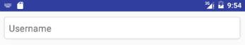
Here’s an example of drawing a rounded rectangle with a border in res/layout/drawable/solid_color_shape.xml:
and then applied to a TextView using the background property:
and the resulting view looks like:
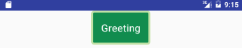
Note that drawables can be applied to any view and are usually set with the background property referencing the drawable resource.
We can create a border programmatically
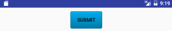
Gradient Colored Shapes
Shapes also support gradients backgrounds as well as supporting properties such as startColor , centerColor , endColor , angle . Different gradients such as radial , linear or sweep can be selected using the type property.
Here’s an example of a simple linear gradient shape specified in res/layout/drawable/gradient_shape.xml:
applied to a Button and the resulting view looks like:
On Android, colors are can be specified as RGB or ARGB. In RGB you have two characters for every color (red, green, blue), and in ARGB you have two additional chars for the alpha channel. Android uses hexadecimal ARGB values, which are formatted as #AARRGGBB. That first pair of letters, the AA, represent the alpha channel.
Following is some useful opacity values
- 100% — FF
- 95% — F2
- 90% — E6
- 85% — D9
- 80% — CC
- 75% — BF
- 70% — B3
- 65% — A6
- 60% — 99
- 55% — 8C
- 50% — 80
- 45% — 73
- 40% — 66
- 35% — 59
- 30% — 4D
- 25% — 40
- 20% — 33
- 15% — 26
- 10% — 1A
- 5% — 0D
- 0% — 00
We can create a gradient drawable programmatically
Line
Line is most often used as a visual separator between different sections or parts of the app and can make it easier to use. One important thing to note is that this line always takes up the entire width of the containing view.
First, let’s look at the simplest example of a line, a simple solid-black line. Create res/drawable/shape_black_line.xml file.
Apply in layout
Some important things to keep in mind when creating a line:
- The width attribute on the stroke element defines the height of the line.
- The height attribute on the size element defines the height of the entire drawable.
- When the line is drawn it is centered vertically in the drawable.
- If the height is the same or smaller than the stroke width then the line won’t show up.
- You can omit the height attribute, but if you do you need to take care to make sure that every view that uses this line specifies a height larger than the stroke width
It is also possible to create a dashed line. To do so, we specify the dashWidth and dashGap attributes on the stroke element. Create res/drawable/shape_dotted_green_line.xml file.
Round badge
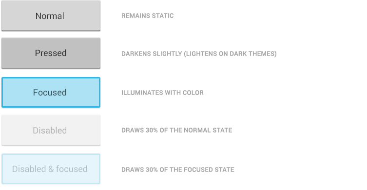
State List Drawables
A StateListDrawable is a drawable object defined in XML that uses several different items to represent the same graphic, depending on the state of the object. For example, a Button widget can exist in one of several different states (pressed, focused, or neither) and, using a state list drawable, you can provide a different background image for each state. The state list supports different view states such as android:state_pressed , android:state_focused , android:state_enabled , android:state_selected , among many others. The illustration below shows all the major states that can be represented:
For example, a state list XML for a Button background might look like the following in a file such as res/drawable/selector_button_bg:
Now, when the view (i.e Button ) is pressed or focused, the drawable used for the view will change accordingly. Note that any view can have a state selector, but the most common uses are with Button s and ListView items. There are also color state selectors which allow a color to be chosen based on view state such as in a file named res/color/button_text.xml:
and applied to textColor property of a Button in a layout file:
Also we can use just shape . Define layer-list in res/drawable/button_gradient.xml.
Using state lists allows us to easily define dynamic views that respond to pressed, checked, enabled or other related states.
Following is example of use android:state_pressed for EditText .
Define selector in res/drawable/et_style.xml.
Layer List Drawables
A LayerDrawable is a drawable object that manages an array of other drawables. Each drawable in the list is drawn in the order of the list — the last drawable in the list is drawn on top. Each drawable is represented by an element inside a single element.
The LayerList can be used to draw multiple other drawables (shapes, images, etc) and position them in relationship to one another. The layers are placed on top of one another by default with the last item being drawn on the top. Layers can then have their coordinates shifted using the left, right, top, and bottom properties.
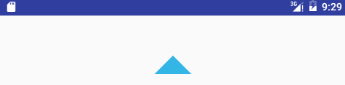
Android triangle
Create arrow_up.xml file in drawables directory with contents:
The idea is to create rectangle shape ( ), fill with gray solid color ( ), rotate it 45 degrees ( ) and move it over X and Y axis ( pivotX and pivotY ) in a way that only half of the rectangle is visible (cut along the diagonal).
We also added thick border ( ) with transparent color. This is because our arrow is a Button , so the invisible part around is needed to ease the click (it enlarges click detection area size).
The usage is as simple as any other xml drawable shape. It is just enough to set it as view background . Here is Button example:
If you need arrow pointing in other direction, you can just rotate it. Here is arrow down:
- scalable, because you can change its size as you wish, without providing bigger or smaller png files for each screen density. And there is no «pixelization» visible regardless of scale used.
- customizable, because you can easier adjust its color to better fit your UI or use it in other project – no need to regenerate png file and change it in project. Just change the xml attribute.
Card with shadow
A card is nothing more than a layout or a view with a background drawable. And that drawable can be defined in res/drawable/layer_card_background.xml XML as a layer drawable.
The first item in the layer-list defines what will be the card’s shadow. The second item in the layer-list is the main content for the card. You can turn any view or layout into a card by setting the background to the layer_card_background drawable.
TextView with border at top and bottom
Create an xml drawable such as res/drawable/textlines.xml and assign this as a TextView ‘s background property.
Define layer-list in res/drawable/textlines.xml.
Button with border at bottom
Define layer-list in res/drawable/button_stroke.xml.
If you want to remove shadow for button add style=»?android:attr/borderlessButtonStyle» .
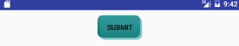
Button with shadow
Define layer-list in res/drawable/shadow.xml.
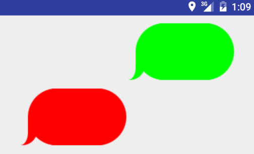
Several shapes
The following layer list draws several shapes in relation to each other:
and this results in the following:
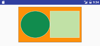
Keep in mind that the items in a LayerList can also be images or any other type of drawable. You can use this to create more complex drawings and overlay multiple drawables on top of each other.
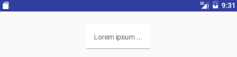
A NinePatch is a PNG image in which you can define stretchable regions that are stretched when the content within the View exceeds the normal image bounds. You typically assign this type of image as the background of a View which has its width set to wrap_content . The most common use is a Button that has to stretch based on the text displayed inside.
As you can see, you have guides on each side of your image. The top and left guides are for scaling your image, while the right and bottom guides define the fill area. The top and left guides are used to define the scalable portion of your image — left for scaling height, top for scaling width. Using a Button image as an example, this means the Button can stretch horizontally and vertically within the black portion and everything else, such as the corners, will remain the same size.
So, a valid nine-patch image file is simply a PNG image in which the outer 1 pixel contains only either black or transparent pixels. The black pixels on each side define something about how the image will stretch and wrap the content inside:
- Left side. Black pixels here define areas where the image should stretch vertically. The pixels in these areas will be stepped and repeated to accomplish the stretch.
- Top side. Black pixels here define areas where the image should stretch horizontally. The pixels in these areas will be stepped and repeated to accomplish the stretch.
- Right side. Black pixels here define the vertical content area, which is the area where the view’s content will display. In effect, it is defining the top and bottom padding values, but inherent to the background image. • Bottom side. Black pixels here define the horizontal content area, which is the area where the view’s content will display. In effect, it is defining the left and right padding values, but inherent to the background image. This must contain a single line of solid pixels defining the area.
The black guide lines are cut-off/removed from your image — they won’t show in the app. Guides must only be one pixel wide, so if you want a 48×48 button, your png will actually be 50×50. Anything thicker than one pixel will remain part of your image. Your guides must be solid black (#000000). Also you should keep in mind that remaining area of the one-pixel outline must be completely transparent. This includes the four corners of the image — those should always be clear.
Fill area guides are optional and provide a way define the area for stuff like your text label. Fill determines how much room there is within your image to place text, or an icon, or other things.
NinePatch are images that have a .9.png file extension, which signifies that this is a stretchable PNG image. The file is no different from a normal PNG file except that you will add thin black lines to indicate the vertical and horizontal «stretchable» and «fill» areas for the image. Android will not show these guide lines, which are used to determine how the image should be rendered.
An example of a 9-patch image is embedded below (left is the 9patch graphic, right is an example of use in an app):
A NinePatch is defined and saved in the drawable folder and setting the background works the same as with any image:
Android Studio comes with the ability to edit 9-patch files directly. Your PNG file simply needs to be saved with the .9.png extension in the drawable folder, and the 9-patch editor will display instead of the normal image editor. You can use the mouse to select the regions to be stretched (use Shift and click while dragging the mouse to erase the region), and the preview pane on the right displays how images will be rendered depending on the text inside.
Transition Drawables allow to define transitions which lets us display a smooth cross-fade effect between two pictures, for example.
Firstly, we’ll need to add 2 pictures to the drawable directory of the project. In my case, they are cat1.jpg and cat2.jpg, and I put both of them in res/drawable-hdpi/ directory.
Add an xml file in the same directory, call it transition.xml. Here we will add a transition node with 2 item nodes inside, each representing an image:
Now go to activity_main.xml layout file. Add an ImageView , set its source to the first image:
When that’s done, go to MainActivity.java class and declare 2 variables — instances of ImageView and TransitionDrawable .
In the onCreate() function of the Activity, set the image value to the ImageView we declared in activity_main.xml. Set trans value to the transition resource we created in the drawable directory:
Now add a click listener to the ImageView object. In the event of a click, use the setImageDrawable() method to apply the transition resource to the image. Then we call the reverseTransition() method of the transition, passing 1000 as the parameter, which is the effect time.
Instead of reverseTransition() , you can call startTransition() , which always starts with the first layer fading out and the second layer fading it. The reverseTransition() method handles the transition both ways.
Using level list drawable, drawable attributes of a view can be set to deferent drawables at run time by calling setLevel on Drawable object and passing level value to it. The level value points to a drawable in the level list drawable.
You can define level list drawable xml with different drawable items setting max and min values for each drawable. At run time, depending on the value passed to setLevel method, a drawable from the level drawable list will be picked and displayed.
Below example defines level list xml with three dawable items with different levels and level ranges. On clicking a button, level is incremented by calling setLevel on Drawable that will make it show corresponding drawable from the level list. Every time the button is clicked, image will be changed to reflect level value.
Using scale drawable, you can specify how a drawable can be scaled depending on the level by setting scale height, scale width and scale gravity. Below is an example scale drawable which is displayed in image view. On clicking a button, the drawable’s level will be increased by calling setLevel and passing level. As the level increases, the drawable that is displayed in ImageView will scale.
Источник