- Layout
- Что такое Layout
- Виды разметок
- Комбинирование
- Программный способ создания разметки
- Android layout into layout
- Основы верстки для нативных андроид приложений
- FrameLayout
- LinearLayout
- RelativeLayout
- TableLayout
- Alternate Layouts
- Стили
- Build a Responsive UI with ConstraintLayout Part of Android Jetpack.
- Constraints overview
- Add ConstraintLayout to your project
- Groovy
- Kotlin
- Groovy
- Kotlin
- Convert a layout
- Create a new layout
- Add or remove a constraint
- Parent position
- Order position
- Alignment
- Baseline alignment
- Constrain to a guideline
- Constrain to a barrier
- Adjust the constraint bias
- Adjust the view size
- Set size as a ratio
- Adjust the view margins
- Control linear groups with a chain
- Automatically create constraints
- Keyframe animations
- Additional resources
Layout
Что такое Layout
При разработке первых приложений мы уже встречали элемент LinearLayout, который позволяет группировать дочерние элементы в одну линию в автоматическом режиме. Существуют и другие типы контейнеров, позволяющие располагать элементы разными способами. Пришло время познакомиться с ними поближе.
Компоновка (также используются термины разметка или макет) хранится в виде XML-файла в папке /res/layout. Это сделано для того, чтобы отделить код от дизайна, как это принято во многих технологиях (HTML и CSS). Кроме основной компоновки для всего экрана, существуют дочерние элементы компоновки для группы элементов. По сути, компоновка – это некий визуальный шаблон для пользовательского интерфейса вашего приложения, который позволяет управлять элементами управления, их свойствами и расположением. В своей практике вам придется познакомиться со всеми способами размещения. Поэтому здесь мы рассмотрим только базовую часть теории, чтобы вы поняли саму сущность разметки. Кроме того, разметку можно создавать программным способом, который будет описан в конце статьи. Если вы будет обращаться к элементам управления через Java-код, то необходимо присваивать элементам уникальный идентификатор через атрибут android:id. Сам идентификатор назначается через выражение @+id/your_value. После этого вы можете обращаться к элементу через код при помощи метода findViewById(R.id.your_value).
Android Studio включает в себя специальный редактор для создания разметки двумя способами. Редактор имеет две вкладки: одна позволяет увидеть, как будут отображаться элементы управления, а вторая – создавать XML-разметку вручную.
Создавая пользовательский интерфейс в XML-файле, вы можете отделить представление приложения от программного кода. Вы можете изменять пользовательский интерфейс в файле разметки без необходимости изменения вашего программного кода. Например, вы можете создавать XML-разметки для различных ориентаций экрана мобильного устройства (portrait, landscape), размеров экрана и языков интерфейса.
Каждый файл разметки должен содержать только один корневой элемент компоновки, который должен быть объектом View или ViewGroup. Внутри корневого элемента вы можете добавлять дополнительные объекты разметки или виджеты как дочерние элементы, чтобы постепенно формировать иерархию элементов, которую определяет создаваемая разметка.
Виды разметок
Существует несколько стандартных типов разметок:
Все описываемые разметки являются подклассами ViewGroup и наследуют свойства, определённые в классе View.
Комбинирование
Компоновка ведёт себя как элемент управления и их можно группировать. Расположение элементов управления может быть вложенным. Например, вы можете использовать RelativeLayout в LinearLayout и так далее. Но будьте осторожны: слишком большая вложенность элементов управления вызывает проблемы с производительностью.
Можно внедрить готовый файл компоновки в существующую разметку при помощи тега :
Подробнее в отдельной статье Include Other Layout
Программный способ создания разметки
Для подключения созданной разметки используется код в методе onCreate():
Естественно, вы можете придумать и свое имя для файла, а также в приложениях с несколькими экранами у вас будет несколько файлов разметки: game.xml, activity_settings.xml, fragment_about.xml и т.д.
В большинстве случаев вы будете использовать XML-способ задания разметки и подключать его способом, указанным выше. Но, иногда бывают ситуации, когда вам понадобится программный способ (или придётся разбираться с чужим кодом). Вам доступны для работы классы android.widget.LinearLayout, LinearLayout.LayoutParams, а также Android.view.ViewGroup.LayoutParams, ViewGroup.MarginLayoutParams. Вместо стандартного подключения ресурса разметки через метод setContentView(), вы строите содержимое разметки в Java, а затем уже в самом конце передаёте методу setContentView() родительский объект макета:
Число макетов постоянно меняется. Например, недавно появились новые виды CoordinatorLayout и ConstraintLayout. Кроме стандартных элементов разметки существуют и сторонние разработки.
Источник
Android layout into layout
Одна layout может содержать другую layout. Для этого применяется элемент include .
Например, добавим в папку res/layout два файла layout, которые пусть будут называться text_panel.xml и button_panel.xml :
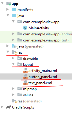
В файле text_panel.xml определим следующий код:
По сути здесь просто определено поле TextView для вывода текста.
В файле button_panel.xml определим следующую разметку:
Здесь определена кнопка, нажатия которой мы будем обрабатывать.
Основным файлом разметки, который определяет интерфейс приложения, по-прежнему является activity_main.xml . Изменим его:
С помощью ConstraintLayout весь интерфейс здесь организуется в виде вертикального стека. С помощью элементов include внутрь ConstraintLayout добавляется содержимое файлов text_panel.xml и button_panel.xml. Для указания названия файла применяется атрибут layout .
Это все равно, что если бы мы напрямую вместо элемента include добавили содержимое файлов. Однако такой способ имеет свои преимущества. Например, какая-то часть разметки, группа элементов управления может повторяться в различных activity. И чтобы не определять по сто раз эти элементы, можно вынести их в отдельный файл layout и с помощью include подключать их.
После добавления в ConstraintLayout к элементам include можно применять все те стандартные атрибуты, которые применяются в этом контейнере к вложенным элементам, например, настроить размеры, расположение. Также стоит отметить, что добавлять внешние layout можно не только в ConstraintLayout, но и в другие контейнеры (LinearLayout, RelativeLayout и т.д.)
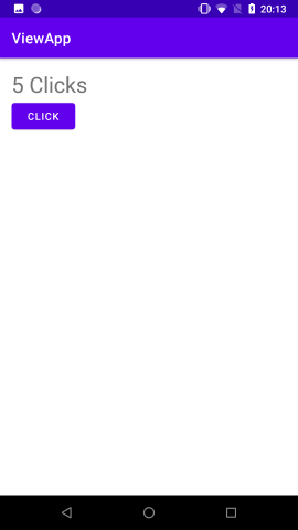
Также изменим код MainActivity :
В MainActivity мы можем обращаться к элементам во вложенных файлах layout. Например, мы можем установить обработчик нажатия кнопки, в котором при нажатии изменять текст в TextView.
При этом мы несколько раз можем добавлять в один файл layout другой файл layout. Для этого вначале изменим файл button_panel.xml следующим образом:
И изменим файл activity_main.xml :
Теперь файл button_panel.xml добавляется два раза. Важно, что при добавлении этого файла каждому элементу include присвоен определенный id. По этому id мы сможем узнать, о каком именно элементе include идет речь.
Также изменим MainActivity:
Здесь вначале мы получаем отдельные элементы include по id. Затем в рамках этих элементов получаем кнопку. После этого мы можем установить у кнопко любой текст и повесить обработчик события нажатия. И таким образом, поведение обеих кнопок будет различаться.
Источник
Основы верстки для нативных андроид приложений
( пользоваться не рекомендуется, deprecated )
AbsoluteLayout — означает что каждый элемент верстки будет иметь абсолютную позицию относительно верхнего левого угла экрана задаваемую с помощью координат x и y. Т.е. верхнийлевый угол экрана при AbsoluteLayout имеет координаты x = 0, y = 0.
Позиция указывается в атрибутах элемента android:layout_x и android:layout_y.
Пример кода:

FrameLayout
FrameLayout — тип верстки внутри которого может отображаться только один элемент в строке. Т.е. если внутри FrameLayout вы поместите несколько элементов, то следующий будет отображаться поверх предыдущего.
Пример кода:
LinearLayout
LinearLayout — тип верстки при котором область верстки делится на строки и в каждую строку помещается один элемент. Разбиение может быть вертикальное или горизонтальное, тип разбиения указывается в атрибуте LinearLayout android:orientation. Внутри верстки возможно комбинировать вертикальную и горизонтальную разбивки, а кроме того, возможна комбинация нескольких разных типов верстки например использование LinearLayout внутри FrameLayout.
Пример вертикальной разбивки LinearLayout:
Пример горизонтальной разбивки LinearLayout:
Комбинация нескольких LinearLayout:
RelativeLayout
RelativeLayout — тип верстки при котором позиционирование элементов происходит относительно друг друга и относительно главного контейнера.
За то, каким образом будут позиционироваться элементы отвечают следующие атрибуты:
Атрибуты позиционирования относительно контейнера
- android:layout_alignParentBottom – Низ элемента находится внизу контейнера
- android:layout_alignParentLeft – Левая часть элемента прилегает к левой части контейнера
- android:layout_alignParentRight – Правая часть элемента прилегает к правой части контейнера
- android:layout_alignParentTop – Элемент находится в верхней части контейнера
- android:layout_centerHorizontal – Элемент позиционируется по центру относительно горизонтального размера контейнера
- android:layout_centerInParent – Элемент позиционируется по центру относительно горизонтального и вертикального размеров размера контейнера
- android:layout_centerVertical – Элемент позиционируется по центру относительно вертикального размера контейнера
Атрибуты позиционирования относительно других элементов.
В качестве значений этих атрибутов ставятся id элемента относительно которого будет производится позиционирование.
android:layout_above – Распологает элемент над указанным
android:layout_below – Распологает элемент под указанным
android:layout_toLeftOf – Распологает элемент слева от указанного
android:layout_toRightOf – Распологает элемент справа от указанного
Выравнивание относительно других элементов.
android:layout_alignBaseline – Выравнивает baseline элемента с baseline указаннго элемента
android:layout_alignBottom – Выравнивает низ элемента по низу указанного элемента
android:layout_alignLeft – Выравнивает левый край элемента с левым краем указанного элемента
android:layout_alignRight – Выравнивает правый край элемента с правым краем указанного элемента
android:layout_alignTop – Выравнивает верхнюю часть элемента в соответствие с верхней частью указанного элемента
TableLayout
TableLayout — табличная верстка.
Организует элементы в строки и столбцы таблицы.
Для организации строк служит таг
Alternate Layouts
Alternate Layouts — альтернативная верстка. Позволяет использовать различную верстку для различных ориентаций экрана.
XML для альтернативной верстки помещается в папки проекта:
res/layout-land – альтернативная верстка для landscape UI
res/layout-port –альтернативная верстка для portrait UI
res/lauout-square – альтернативная верстка для square UI
и перед тем как получить макет из res/lauout система проверяет наличие файлов в этих папках.
И в завершении немного о стилях.
Стили
Во первых стили элемента могут быть описаны в атрибутах самого элемента.
Например:
Кроме того стили можно вынести в отдельный xml файл и сохранить его в папке res/values/
Напимер:
Если мы вынесем стили в отдельный файл, то для описания стилей элемента будем использовать атрибут style.
Источник
Build a Responsive UI with ConstraintLayout Part of Android Jetpack.
ConstraintLayout allows you to create large and complex layouts with a flat view hierarchy (no nested view groups). It’s similar to RelativeLayout in that all views are laid out according to relationships between sibling views and the parent layout, but it’s more flexible than RelativeLayout and easier to use with Android Studio’s Layout Editor.
All the power of ConstraintLayout is available directly from the Layout Editor’s visual tools, because the layout API and the Layout Editor were specially built for each other. So you can build your layout with ConstraintLayout entirely by drag-and-dropping instead of editing the XML.
This page provides a guide to building a layout with ConstraintLayout in Android Studio 3.0 or higher. If you’d like more information about the Layout Editor itself, see the Android Studio guide to Build a UI with Layout Editor.
To see a variety of layouts you can create with ConstraintLayout , check out the Constraint Layout Examples project on GitHub.
Constraints overview
To define a view’s position in ConstraintLayout , you must add at least one horizontal and one vertical constraint for the view. Each constraint represents a connection or alignment to another view, the parent layout, or an invisible guideline. Each constraint defines the view’s position along either the vertical or horizontal axis; so each view must have a minimum of one constraint for each axis, but often more are necessary.
When you drop a view into the Layout Editor, it stays where you leave it even if it has no constraints. However, this is only to make editing easier; if a view has no constraints when you run your layout on a device, it is drawn at position [0,0] (the top-left corner).
In figure 1, the layout looks good in the editor, but there’s no vertical constraint on view C. When this layout draws on a device, view C horizontally aligns with the left and right edges of view A, but appears at the top of the screen because it has no vertical constraint.
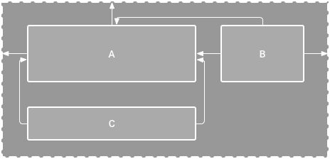
Figure 1. The editor shows view C below A, but it has no vertical constraint
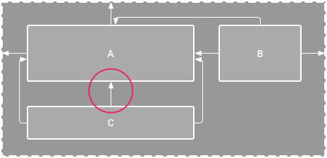
Figure 2. View C is now vertically constrained below view A
Although a missing constraint won’t cause a compilation error, the Layout Editor indicates missing constraints as an error in the toolbar. To view the errors and other warnings, click Show Warnings and Errors . To help you avoid missing constraints, the Layout Editor can automatically add constraints for you with the Autoconnect and infer constraints features.
Add ConstraintLayout to your project
To use ConstraintLayout in your project, proceed as follows:
- Ensure you have the maven.google.com repository declared in your top-level build.gradle file:
Groovy
Kotlin
Groovy
Kotlin
Now you’re ready to build your layout with ConstraintLayout .
Convert a layout
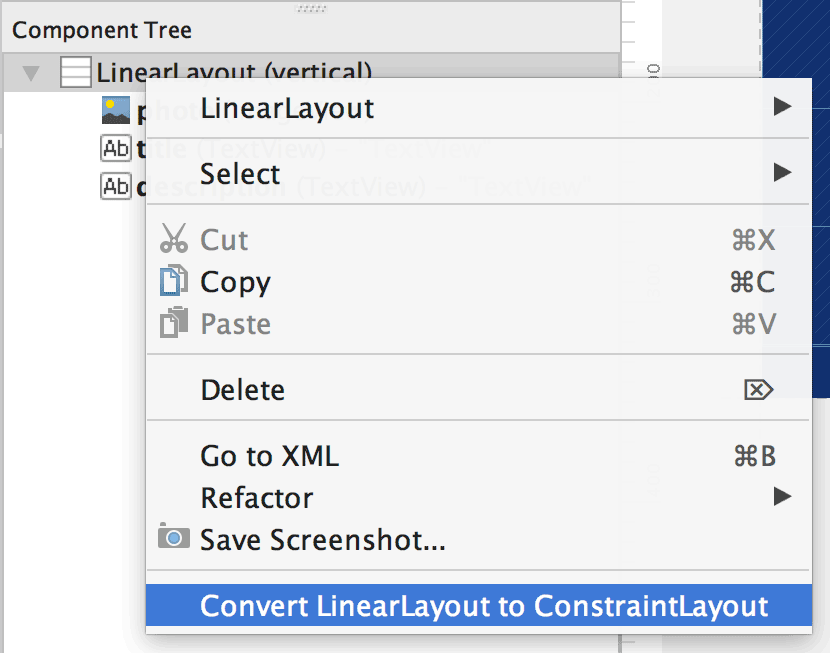
Figure 3. The menu to convert a layout to ConstraintLayout
To convert an existing layout to a constraint layout, follow these steps:
- Open your layout in Android Studio and click the Design tab at the bottom of the editor window.
- In the Component Tree window, right-click the layout and click Convert layout to ConstraintLayout.
Create a new layout
To start a new constraint layout file, follow these steps:
- In the Project window, click the module folder and then select File > New > XML > Layout XML.
- Enter a name for the layout file and enter «androidx.constraintlayout.widget.ConstraintLayout» for the Root Tag.
- Click Finish.
Add or remove a constraint
To add a constraint, do the following:
Video 1. The left side of a view is constrained to the left side of the parent
Drag a view from the Palette window into the editor.
When you add a view in a ConstraintLayout , it displays a bounding box with square resizing handles on each corner and circular constraint handles on each side.
Click one of the Create a connection buttons in the Layout section of the Attributes window, as shown in figure 4.

Figure 4. The Layout section of the Attributes window lets you create connections.
When the constraint is created, the editor gives it a default margin to separate the two views.
When creating constraints, remember the following rules:
- Every view must have at least two constraints: one horizontal and one vertical.
- You can create constraints only between a constraint handle and an anchor point that share the same plane. So a vertical plane (the left and right sides) of a view can be constrained only to another vertical plane; and baselines can constrain only to other baselines.
- Each constraint handle can be used for just one constraint, but you can create multiple constraints (from different views) to the same anchor point.
You can delete a constraint by doing any of the following:
- Click on a constraint to select it, and then press Delete .
Press and hold Control ( Command on macOS), and then click on a constraint anchor. Note that the constraint turns red to indicate that you can click to delete it, as shown in figure 5.

Figure 5. A red constraint indicates that you can click to delete it.
In the Layout section of the Attributes window, click on a constraint anchor, as shown in figure 6.

Figure 6. Click on a constraint anchor to delete it.
Video 2. Adding a constraint that opposes an existing one
If you add opposing constraints on a view, the constraint lines become squiggly like a spring to indicate the opposing forces, as shown in video 2. The effect is most visible when the view size is set to «fixed» or «wrap content,» in which case the view is centered between the constraints. If you instead want the view to stretch its size to meet the constraints, switch the size to «match constraints»; or if you want to keep the current size but move the view so that it is not centered, adjust the constraint bias.
You can use constraints to achieve different types of layout behavior, as described in the following sections.
Parent position
Constrain the side of a view to the corresponding edge of the layout.
In figure 7, the left side of the view is connected to the left edge of the parent layout. You can define the distance from the edge with margin.
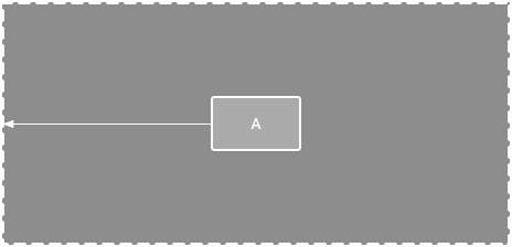
Figure 7. A horizontal constraint to the parent
Order position
Define the order of appearance for two views, either vertically or horizontally.
In figure 8, B is constrained to always be to the right of A, and C is constrained below A. However, these constraints do not imply alignment, so B can still move up and down.
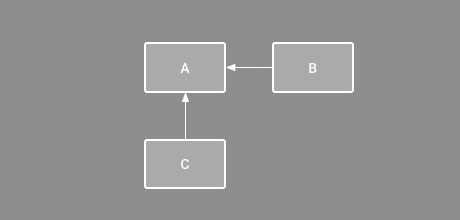
Figure 8. A horizontal and vertical constraint
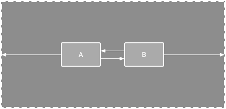
Alignment
Align the edge of a view to the same edge of another view.
In figure 9, the left side of B is aligned to the left side of A. If you want to align the view centers, create a constraint on both sides.
You can offset the alignment by dragging the view inward from the constraint. For example, figure 10 shows B with a 24dp offset alignment. The offset is defined by the constrained view’s margin.
You can also select all the views you want to align, and then click Align in the toolbar to select the alignment type.
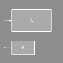
Figure 9. A horizontal alignment constraint
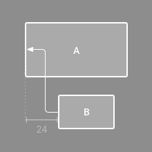
Figure 10. An offset horizontal alignment constraint
Baseline alignment
Align the text baseline of a view to the text baseline of another view.
In figure 11, the first line of B is aligned with the text in A.
To create a baseline constraint, right-click the text view you want to constrain and then click Show Baseline. Then click on the text baseline and drag the line to another baseline.
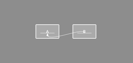
Figure 11. A baseline alignment constraint
Constrain to a guideline
You can add a vertical or horizontal guideline to which you can constrain views, and the guideline will be invisible to app users. You can position the guideline within the layout based on either dp units or percent, relative to the layout’s edge.
To create a guideline, click Guidelines in the toolbar, and then click either Add Vertical Guideline or Add Horizontal Guideline.
Drag the dotted line to reposition it and click the circle at the edge of the guideline to toggle the measurement mode.
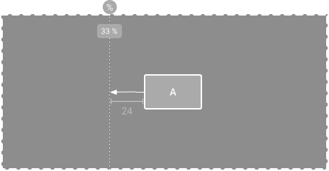
Figure 12. A view constrained to a guideline
Constrain to a barrier
Similar to a guideline, a barrier is an invisible line that you can constrain views to. Except a barrier does not define its own position; instead, the barrier position moves based on the position of views contained within it. This is useful when you want to constrain a view to the a set of views rather than to one specific view.
For example, figure 13 shows view C is constrained to the right side of a barrier. The barrier is set to the «end» (or the right side in a left-to-right layout) of both view A and view B. So the barrier moves depending on whether the right side of view A or view B is is farthest right.
To create a barrier, follow these steps:
- Click Guidelines in the toolbar, and then click Add Vertical Barrier or Add Horizontal Barrier.
- In the Component Tree window, select the views you want inside the barrier and drag them into the barrier component.
- Select the barrier from the Component Tree, open the Attributes window, and then set the barrierDirection.
Now you can create a constraint from another view to the barrier.
You can also constrain views that are inside the barrier to the barrier. This way, you can ensure that all views in the barrier always align to each other, even if you don’t know which view will be the longest or tallest.
You can also include a guideline inside a barrier to ensure a «minimum» position for the barrier.
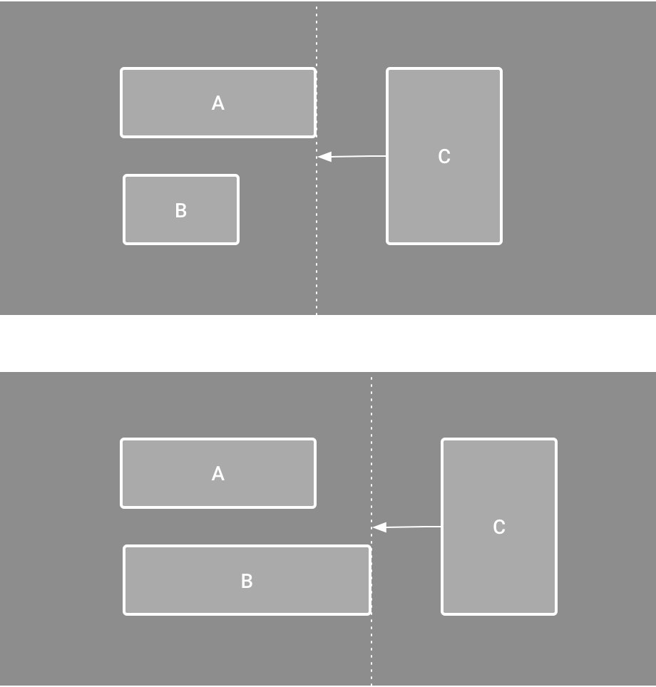
Figure 13. View C is constrained to a barrier, which moves based on the position/size of both view A and view B
Adjust the constraint bias
When you add a constraint to both sides of a view (and the view size for the same dimension is either «fixed» or «wrap content»), the view becomes centered between the two constraints with a bias of 50% by default. You can adjust the bias by dragging the bias slider in the Attributes window or by dragging the view, as shown in video 3.
If you instead want the view to stretch its size to meet the constraints, switch the size to «match constraints».
Video 3. Adjusting the constraint bias
Adjust the view size

Figure 14. When selecting a view, the Attributes window includes controls for 1 size ratio, 2 deleting constraints, 3 height/width mode, 4 margins, and 5 constraint bias. You can also highlight individual constraints in the Layout Editor by clicking on them in the 6 constraint list.
You can use the corner handles to resize a view, but this hard codes the size so the view will not resize for different content or screen sizes. To select a different sizing mode, click a view and open the Attributes window on the right side of the editor.
Near the top of the Attributes window is the view inspector, which includes controls for several layout attributes, as shown in figure 14 (this is available only for views in a constraint layout).
You can change the way the height and width are calculated by clicking the symbols indicated with callout 3 in figure 14. These symbols represent the size mode as follows (click the symbol to toggle between these settings):
- Fixed: You specify a specific dimension in the text box below or by resizing the view in the editor.
- Wrap Content: The view expands only as much as needed to fit its contents.
- Match Constraints: The view expands as much as possible to meet the constraints on each side (after accounting for the view’s margins). However, you can modify that behavior with the following attributes and values (these attributes take effect only when you set the view width to match constraints):
- layout_constraintWidth_default
- spread: Expands the view as much as possible to meet the constraints on each side. This is the default behavior.
- wrap: Expands the view only as much as needed to fit its contents, but still allows the view to be smaller than that if the constraints require it. So the difference between this and using Wrap Content (above), is that setting the width to Wrap Content forces the width to always exactly match the content width; whereas using Match Constraints with layout_constraintWidth_default set to wrap also allows the view to be smaller than the content width.
- layout_constraintWidth_min
This takes a dp dimension for the view’s minimum width.
This takes a dp dimension for the view’s maximum width.
However, if the given dimension has only one constraint, then the view expands to fit its contents. Using this mode on either the height or width also allows you to set a size ratio.
Note: You cannot use match_parent for any view in a ConstraintLayout . Instead use «match constraints» ( 0dp ).

Figure 15. The view is set to a 16:9 aspect with the width based on a ratio of the height.
Set size as a ratio
You can set the view size to a ratio such as 16:9 if at least one of the view dimensions is set to «match constraints» ( 0dp ). To enable the ratio, click Toggle Aspect Ratio Constraint (callout 1 in figure 14), and then enter the width : height ratio in the input that appears.
If both the width and height are set to match constraints, you can click Toggle Aspect Ratio Constraint to select which dimension is based on a ratio of the other. The view inspector indicates which is set as a ratio by connecting the corresponding edges with a solid line.
For example, if you set both sides to «match constraints», click Toggle Aspect Ratio Constraint twice to set the width be a ratio of the height. Now the entire size is dictated by the height of the view (which can be defined in any way) as shown in figure 15.
Adjust the view margins
To ensure that all your views are evenly spaced, click Margin in the toolbar to select the default margin for each view that you add to the layout. Any change you make to the default margin applies only to the views you add from then on.
You can control the margin for each view in the Attributes window by clicking the number on the line that represents each constraint (in figure 14, callout 4 shows the bottom margin is set to 16dp).
Figure 16. The toolbar’s Margin button.
All margins offered by the tool are factors of 8dp to help your views align to Material Design’s 8dp square grid recommendations.
Control linear groups with a chain
Figure 17. A horizontal chain with two views
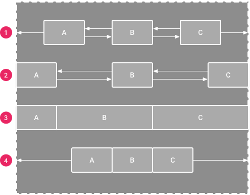
A chain is a group of views that are linked to each other with bi-directional position constraints. The views within a chain can be distributed either vertically or horizontally.
Figure 18. Examples of each chain style
Chains can be styled in one of the following ways:
- Spread: The views are evenly distributed (after margins are accounted for). This is the default.
- Spread inside: The first and last view are affixed to the constraints on each end of the chain and the rest are evenly distributed.
- Weighted: When the chain is set to either spread or spread inside, you can fill the remaining space by setting one or more views to «match constraints» ( 0dp ). By default, the space is evenly distributed between each view that’s set to «match constraints,» but you can assign a weight of importance to each view using the layout_constraintHorizontal_weight and layout_constraintVertical_weight attributes. If you’re familiar with layout_weight in a linear layout, this works the same way. So the view with the highest weight value gets the most amount of space; views that have the same weight get the same amount of space.
- Packed: The views are packed together (after margins are accounted for). You can then adjust the whole chain’s bias (left/right or up/down) by changing the chain’s head view bias.
The chain’s «head» view (the left-most view in a horizontal chain and the top-most view in a vertical chain) defines the chain’s style in XML. However, you can toggle between spread, spread inside, and packed by selecting any view in the chain and then clicking the chain button that appears below the view.
To create a chain, select all of the views to be included in the chain, right-click one of the views, select Chains and then select either Center Horizontally or Center Vertically, as shown in video 4:
Video 4. Creating a horizontal chain
Here are a few other things to consider when using chains:
- A view can be a part of both a horizontal and a vertical chain, making it easy to build flexible grid layouts.
- A chain works properly only if each end of the chain is constrained to another object on the same axis, as shown in figure 14.
- Although the orientation of a chain is either vertical or horizontal, using one does not align the views in that direction. So be sure you include other constraints to achieve the proper position for each view in the chain, such as alignment constraints.
Automatically create constraints
Instead of adding constraints to every view as you place them in the layout, you can move each view into the positions you desire, and then click Infer Constraints to automatically create constraints.
Infer Constraints scans the layout to determine the most effective set of constraints for all views. It makes a best effort to constrain the views to their current positions while allowing flexibility. You might need to make some adjustments to be sure the layout responds as you intend for different screen sizes and orientations.
Autoconnect to parent is a separate feature that you can enable. If enabled, when you add child views to a parent, this feature automatically creates two or more constraints for each view as you add them to the layout, but only when it’s appropriate to constrain the view to the parent layout. Autoconnect does not create constraints to other views in the layout.
Autoconnect is disabled by default. Enable it by clicking Enable Autoconnection to Parent in the Layout Editor toolbar.
Keyframe animations
Within a ConstraintLayout , you can animate changes to the size and position of elements by using ConstraintSet and TransitionManager.
A ConstraintSet is a lightweight object that represents the constraints, margins, and padding of all child elements within a ConstraintLayout . When you apply a ConstraintSet to a displayed ConstraintLayout , the layout updates the constraints of all of its children.
To build an animation using ConstraintSets, specify two layout files which act as a start and end keyframe for the animation. You can then load a ConstraintSet from the second keyframe file and apply it to the displayed ConstraintLayout .
The code example below shows how to animate moving a single button to the bottom of the screen.
Note: With Android Studio 3.6 and higher, the view binding feature can replace findViewById() calls and provides compile-time type safety for code that interacts with views. Consider using view binding instead of findViewById() .
Additional resources
ConstraintLayout is used in the Sunflower demo app.
Content and code samples on this page are subject to the licenses described in the Content License. Java is a registered trademark of Oracle and/or its affiliates.
Источник
- layout_constraintWidth_default