- Android led rgb colors
- Control RGB LEDs Using Android and Arduino
- This is an interesting topic because two ecosystems are mixed together and integrated. By picking a color from an app running on your Android smartphone, we will make an Arduino switch on a RGB LED of that same color.
- Stonez56: Family, Life, Kids, Work, Arduino
- 2015/02/15
- Android control color RGB LED using HC-05 Bluetooth module with Arduino (Part II)
- Android control color RGB LED using HC-05 Bluetooth with Arduino(Part II)
- Here are the App coding screenshot for your reference:
- Part II — Android HC-05 藍芽連線控制彩色 RGB LED
- MIT App Inventor 的程式代碼如下:
- 110 comments:
Android led rgb colors
Новые темы необходимо создавать только в корневом разделе! В дальнейшем они будут обработаны модераторами.
Если Вы выложили новую версию программы, пожалуйста, сообщите об этом модератору нажав на вашем сообщении кнопку «Жалоба».
RGB Control
версия: 0.2 beta
Последнее обновление программы в шапке: 01.04.2018
Краткое описание:
Управление светодиодной лентой через инфракрасный передатчик.
Описание:
Виджеты для управления светодиодной лентой:
*Включение и отключение
*Смена режима
В будущем будет больше)
ДЛЯ РАБОТЫ ПРОГРАММЫ В ТЕЛЕФОНЕ ДОЛЖЕН БЫТЬ УСТАНОВЛЕН ИНФРАКРАСНЫЙ ИЗЛУЧАТЕЛЬ(ПЕРЕДАТЧИК).
Требуется Android: 4.4 и выше
0.1 beta
Первая версия программы
0.2 beta
*Новый виджет смены режима подсветки(FLASH, STROBE, FADE, SMOOTH)
В будущем планирую:
*Добавить поддержку различных пультов
*Виджеты для изменения режима/цвета/яркости подсветки
0.1 beta
Сообщение отредактировал b1ladri — 06.04.18, 15:31
Новая версия: версия: 0.2 beta
Новое:
*Новый виджет смены режима подсветки(FLASH, STROBE, FADE, SMOOTH)
Источник
Control RGB LEDs Using Android and Arduino
This is an interesting topic because two ecosystems are mixed together and integrated. By picking a color from an app running on your Android smartphone, we will make an Arduino switch on a RGB LED of that same color.
Join the DZone community and get the full member experience.
to make everything work there are several aspects to consider: first it is necessary to create an android app so that we can select the color we want. then, we need to send that data to arduino. the data is built by the three colour values (red, green, blue). on the arduino side, we have to create a server that receives the three colours values and controls an rgb led.
as a final result, we will get something like this:
before digging into the project details, it is useful to have a project overview:
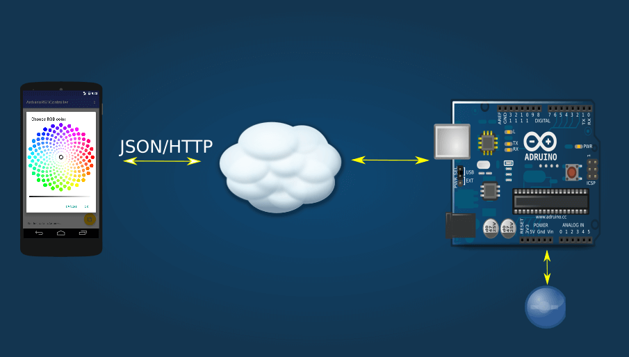
in a previous post we talked about how to turn on and off an led connected to an arduino using an android app , now it is time to make things a little more complex.
to build this project, we need:
- colour picker view
- http client that sends data
- http server to get data
- simple json parser
- rgb led handler
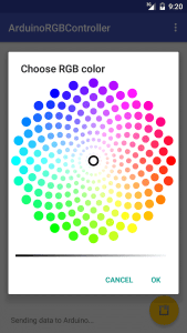
to control rgb led, the first step is creating an android color picker ui so that the user can pick the color to turn on the rgb led. let us start from the final android ui result:
to create this interface we used an interesting open source project called color picker . this component is very easy to use.
at the first step, we create the main layout based on the android floating action button:
now when a user presses the fab, the app will show the color picker dialogue:
it is time to show the color picker dialog that will control the rgb led in the onclick method:
as you can see this component is very simple to use, when the user clicks ok, the app extracts the red, green, and blue components and sends them to arduino.
to send data to arduino, we need to create a simple http client that sends the red, green, and blue components as a json string. arduino will use this information to control the rgb led. the android http client is very simple and it is based on okhttp .
where createjson method is very simple:
it returns the three color values.
the android side is completed, as you can see with a few lines of code we created a nice android app that will control an rgb led connected to arduino.
now the android client side is ready, it is time to build the arduino side. the first step is creating the arduino sketch. this tutorial uses a common anode rgb led, that means the vcc is connected to the anode. if you use a common cathode led the cathode must be connected to the ground.
the arduino sketch is shown below:
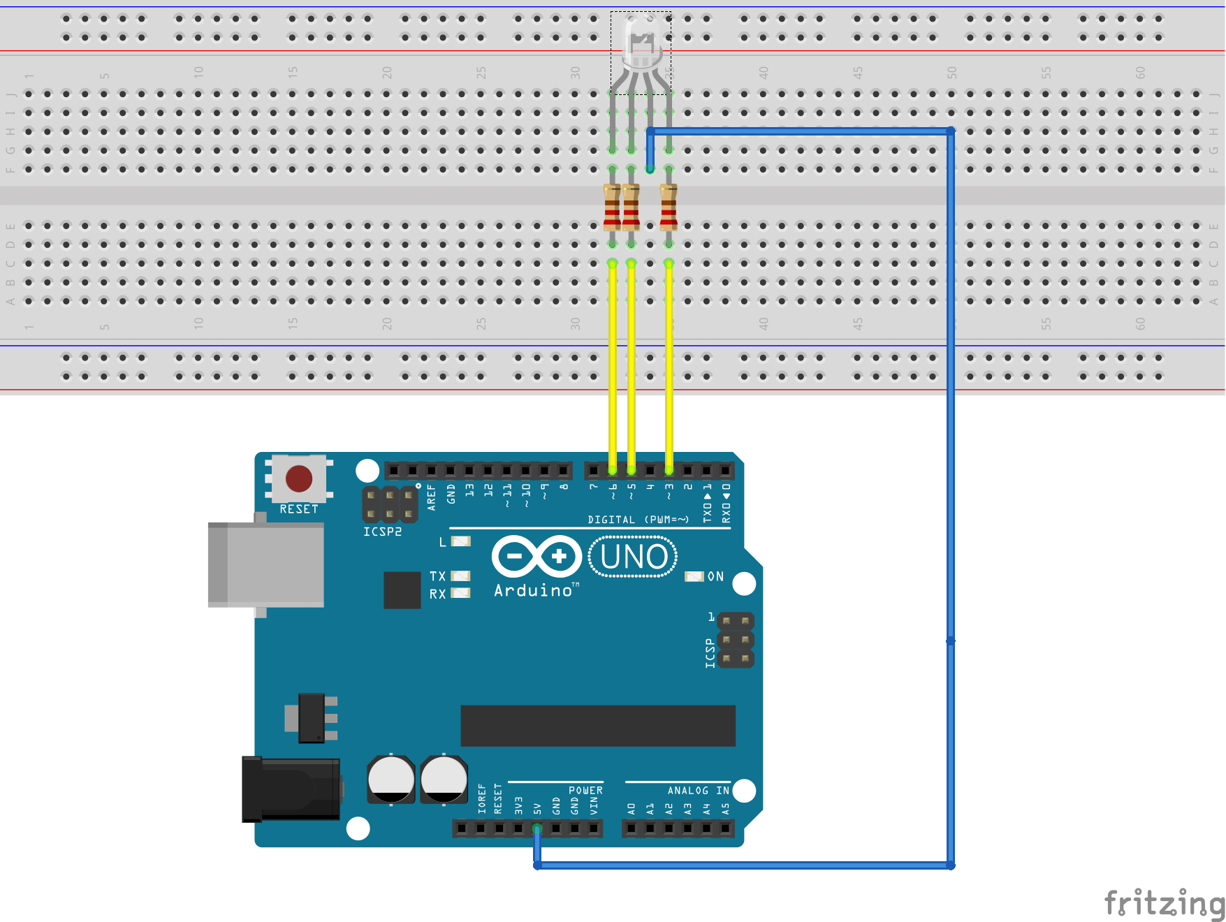
the three led pins are connected to arduino pwm using a 300 ohm resistor. that’s all, the “hardware” part is ready to be used. if you want to test the arduino to know if everything works correctly you can use this arduino sketch.
in the diagram above, the ethernet shield is not shown to simplify the diagram. of course, to connect arduino to the internet, it’s necessary to have an ethernet shield or a wi-fi shield. this tutorial uses the ethernet shield .
now that the “hardware” part is ready, arduino has to accept the http connection so that the android client can send data (the rgb values). it is necessary to build, then, a simple http server that parses the incoming requests and extracts the values.
in the setup method of the sketch, we initialize the arduino pins to control the rgb led and the ethernet ip.
now it is time to accept incoming requests and parse them:
the source code seems to be complex but it is very simple if you look at it carefully. it is always an http arduino server.
the last part is setting the rgb led color:
notice that if we use a common anode , we have to invert the values.
Источник
Stonez56: Family, Life, Kids, Work, Arduino
Family, Life, Kids, Work, Arduino.
2015/02/15
Android control color RGB LED using HC-05 Bluetooth module with Arduino (Part II)
Android control color RGB LED using HC-05 Bluetooth with Arduino(Part II)
You probably have seen my first part of Arduino hardware setup tutorial. If you haven’t please visit here: My previous Arduino (Part I tutorial).
After few weeks of struggling with MIT App Inventor 2, I finally completed my second generation of Color LED Controller V2.0 App.
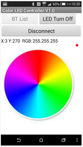
Basically, 2nd generation of Android APP shows a color RGB wheel on the display and you might pick any color on the display to wirelessly change the RGB color accordingly. With glide/drag capability built in the App, you may glide your finger through the color wheel to see RGB LED changes color gradually.
For the Arduino part, all the code stays the same. Yes, I haven’t modified a single line of code in the Arduino.
Please watch the video below to see how it works! 🙂
Here are the App coding screenshot for your reference:
4) Code for touch on the color wheel to change LED color
5) Code for Glide/Drag finger across the color wheel to see the color change accordingly
How RGB Color Code was Processed:==*==*==*====*====*====*====*====*====*====*====*====*====*====*==
In App Inventor, the color code string after [Split Color] will be something like » (255 255 255 255) «. What I need in Arduino is only R, G B, so I have to remove last 255.
*** The last 255 is a string in color code and it will be 255 all the time***
For easier string processing, I replace » «(space) with a «.» (dot).
Then, I send each color code string to Arduino as » 255.255.255) «
In side Arduino, I could split R, G, and B easily with the «.»(dot) and use ending «)»(parenthesis) to check if the color code is complete or not.
==*==*==*====*====*====*====*====*====*====*====*====*====*====*==
After you put all these codes into MIT App Inventor 2, you should able to build the code on your PC/Mac to generate an Android .APK to place on your Android phone to test it out with Arduino.
Please do not ask me to post the original code here for you to download. If I do so, no one would download my App from Android Play Store! 😉
If you don’t want to create this App yourself, please Download this App here!
Part II — Android HC-05 藍芽連線控制彩色 RGB LED
MIT App Inventor 的程式代碼如下:
4) 這組程式碼是用來回應點選的顏色並改變 LED 顏色
110 comments:
excellent contribution friend uses a lot of information but the images are not loading properly, greetings and hope you can solve the problem thanks
Hi LUIS,
Are all the images showed up properly for you?
thank you very much for your help, I would like to know as well as I do to define the colorpicked and previouscolor that are global variables, if I can help I would greatly appreciate it.
Benjamin Vallet & Luis Carlos, it looks like there are some codes missing. let me check it out and get back to you!
Sorry for the delay, please set these variables as below:
initialize global: ColorPicked to “7”
initialize global PreviousColor to “p”
I’ve added the missing global variables back to the blog.
Check them out!
hello, can you say how do you define global variables color picked and previous color?
thanks for the answer.
Benjamin Vallet & Luis Carlos, it looks like there are some codes missing. let me check it out and get back to you!
Sorry for the delay, please set these variables as below:
initialize global: ColorPicked to “7”
initialize global PreviousColor to “p”
hello cordial greeting, thanks for answering to our questions but I have one more, have realized the whole part of the programming in the appinventor but to the moment to prove the part of the code RGB it me appears 255 that it should not appear also appears between parentheses and not separated by points, not that I am doing bad
Well, in App Inventor, the color code string after [Split Color] will be something like «(255 255 255 255)». What I need in Arduino is only R, G B, so I have to remove last 255.
*** The last 255 is a string in color code and it will be 255 all the time***
For easier string processing, I replace » «(space) with a «.» (dot).
Then, I send each color code string to Arduino as «255.255.255)»
In side Arduino coding, I split R, G, and B easily with the «.»(dot) and use ending «)»(parenthesis) to check if the color code is complete or not.
I hope this helps!
great thanks for your help, really it served me very much to be able to develop the project. your help was very valuable
Thank u very very much for sharing this project.
Ive been doing this all by myself. but i had so many problems when programming the arduino. I couldnt find a way to read this list «split color» and i was doing it using the command Serial.parseInt() but it only reads separate the data by commas. Is there any possibility that i could do this program without using the library u used?
And then again! THANKS. Sry for my english.
I am not sure about this, but if Serial.parseInt() only read separate data by commas, then you should just replace «.»(dot) with a «,» (comma).
Look at AI2 blocks step (6), about in the middle part, there’s command blocks
***My code was***
Replace all text
Segment » » (space)
Replacement «.» (dot)
***Your code should be***
Replace all text
Segment » » (space)
Replacement «,» (comma)
Then, it should work!
hi. i need you help please.
i have a proble,. when i want to replace » «(space) with a «.» (dot).
Then i get this: example: 255 255 255 i get .2.5.5..2.5.5..2.5.5
example 2: 150 40 10 i get .1.5.0..4.0..1.0
it’s like the numbers were separated.
help me please
First, count how long is the string you are spliting. You r example string «255 255 255» does not have any space between «255». I really do not understand why it becomes «2.5.5».
Save your code and send it to me and let me take a look.
i found the way.. first i replaced space » » with «.» then 2.5.5. .2.5.5. .2.5.5 next i replaced «. .» with «,» then 2.5.5,2.5.5,2.5.5 next i replaced again «.» with space» «
then 255,255,255
😉 thanks for you time
Glad that works for your!!
This comment has been removed by the author.
a taste to greet it again had not written again because for questions of work I had to leave the project, but now when I have more time great I have recaptured it.
I have had several problems at the time of obtaining the code rgb to send it to the arduino, have tried to modify the blocks of appinventor and have come across with a big problem. already to the moment to give me the code rgb he does not place me separated by dot or for commas the replaced one gives of the following form 255 255 255 » » with one «.» and nevertheless a form does not even give them.
I would like to have your mail to send to you a few images so that he observes her and be able to help me
Hi Luis, leave your email here. I will try to reply your questions.
amigo podemia me ajudar com o aplicativo?
I really appreciate your article. I am an industrial designer, and I just started trying to learn app development and arduino programing. Unfortunately, when I tried to recreate your code in App Inventor, I ran into a few problems. You call for a global variable called «ColorPicked» but I don’t see where you initialize it. I also am not sure what element «Status» is tied to. I tried creating a notification called «Status», but it does not allow me to set it to text like you can. Is there any way you could export and upload the AIA file? Also, I can’t find your arduino code. I looked under both part 1 and part 2. Thanks.
P.S. If I hear back from you, and if you don’t mind, I’d like to pick your brain on the best way to implement additional functionality (i.e. incorporating a slider and servo control, creating programmed color shows that run on a timer, etc.)
Arduino code is in Tutorial Part I.
In App Inventor2:
initialize global: ColorPicked to “7”
initialize global PreviousColor to “p”
Источник


