- Русские Блоги
- Как управлять Arduino с телефона Android с модулем Bluetooth
- Отправить пример
- Пример получения
- Шаг 1: список проводов и запчастей
- Шаг 2: код Arduino
- Шаг 3. Приложение и изобретатель приложений
- Шаг 4: Получите данные от Arduino
- Шаг 5: код Arduino для датчика
- Шаг 6: прием данных — мобильный терминал
- Bluetooth HC-06 и ардуино. Приложение андроид для управления Реле с телефона.
- Не забывайте подписываться на канал Youtube и вступайте в группы в Вконтакте и Facebook.
- Всем Пока-Пока. И до встречи в следующем проекте.
- Martyn Currey
- Mostly Arduino stuff
- Create A Bluetooth Joypad With App Inventor 2
- App Inventor 2
- Design
- Control codes
- App Inventor 2 and Bluetooth
- Screen Size
- Creating the Layout
- Building The App
- Bluetooth Connection
- Button Clicks
- Arduino
- The Circuit
- App In Action
- Things To Try Next
- Downloads
- 7 thoughts on “ Create A Bluetooth Joypad With App Inventor 2 ”
Русские Блоги
Как управлять Arduino с телефона Android с модулем Bluetooth
оригинал:How to Control Arduino Board Using an Android Phone and a Bluetooth Module
OF: керимил
Перевод: Ань Сян
Обзор: Ту Минь, обратите внимание на области Интернета вещей и мобильной разработки, отправляйте отчеты или материалы по электронной почте [email protected] 。
Из этого туториала Вы узнаете, как использовать модуль Bluetooth и приложение из изобретателя MIT (официальный сервер App Inventor) для создания беспроводного соединения между телефоном Android и платой разработки Arduino, а также покажете телефон и Связь между Arduino.
Отправить пример
На следующем рисунке показан пример отправки инструкций из приложения для Android. Он управляет светодиодным переключателем через модуль Bluetooth, и вы можете видеть, что команда может быть отправлена не только через кнопку на интерфейсе приложения, но и через голос. Конкретный контент будет представлен на шагах 1, 2 и 3.

Рисунок 1. Светодиодный индикатор управления приложением Android

Рис. 2. Интерфейс приложения Android.
Пример получения
На рисунке ниже показан пример получения данных с телефона Android. Плата для разработки Arduino использует датчик температуры DS18B20 для получения значения температуры. Приложение Android обновляет значение температуры каждые 15 секунд. Чтобы лучше отобразить эффект, я реализовал голосовую трансляцию с мобильного телефона. Код Arduino и прикладная программа будут подробно описаны в следующих шагах 4, 5 и 6.

Рис. 3. Телефон Android показывает температуру окружающей среды.
Далее я шаг за шагом представлю метод подключения, напишу скетч Arduino, который может отправлять и получать команды, и напишу приложение. Это руководство требует, чтобы вы имели базовые представления об Arduino, знакомы с его IDE, и лучше всего выполнить несколько небольших проектов. В этом случае содержимое этого руководства будет очень легко понять, и вам будет очень легко реализовать последовательную связь с Arduino.
Шаг 1: список проводов и запчастей

Рисунок 4. Схема подключения оборудования в примере отправки.
Способ подключения очень прост, как показано на рисунке выше.
- Плата для разработки Arduino
- Модуль последовательного порта Bluetooth
- LED
- Сопротивление (100 Ом)
- провод
- Макетная плата
На рынке представлено много видов модулей Bluetooth. Вам необходимо ознакомиться с инструкцией по эксплуатации конкретного модуля Bluetooth и выполнить правильное подключение в соответствии с его схемой контактов.
Кроме того, модуль Bluetooth разделен на следующие два уровня в зависимости от расстояния:
- Уровень 1, его дальность около 100 метров (300 футов).
- Уровень 2 с радиусом действия примерно 10 метров (30 футов)
Как вы понимаете, эти два уровня модулей Bluetooth совместимы друг с другом. Только если и мобильный телефон, и модуль Bluetooth имеют уровень 1, может быть достигнута передача на 100 метров. Если есть только один Bluetooth класса 1, то максимальное расстояние передачи будет относительно сокращено и не достигнет 100 метров.
Контакты моего модуля Bluetooth последовательного порта слева: земля, RX, TX, пустой, VCC. Земля и VCC соответственно подключены к земле и выводу + 5V на плате разработки Arduino. В основном мы получаем данные, отправленные мобильным телефоном через модуль Bluetooth, а затем пересылаем данные в Arduino, поэтому нам нужно только подключить контакт TX модуля Bluetooth к контакту RX платы разработки Arduino. Кроме того, подключите PIN2 Arduino к светодиоду для управления светодиодом.
Шаг 2: код Arduino
Ниже приведен код Arduino, который я написал, и вы можете изменить его по своему желанию.
На что следует обратить внимание, так это на скорость передачи данных. Убедитесь, что она соответствует вашему модулю Bluetooth. Рекомендуется внимательно проверить руководство по данным или таблицу AT-команд.
Шаг 3. Приложение и изобретатель приложений

Рисунок 5. Интерфейс App Inventor
Если вы хотите получить приложение и запустить его,адресУстановить после скачивания.
Вам необходимо проверить настройки телефона и разрешить приложениям, отличным от Android Market и Google Play, чтобы вы могли их загрузить.
Если вы хотите изменить приложение, пожалуйстакликните сюдаЧтобы узнать, как подготовить компьютер и установить программное обеспечение App Inventor. После того, как операция будет успешной, я предлагаю вам следовать основному руководству и выполнить одно или два приложения, чтобы попрактиковаться в руках.
кликните сюдаПолучите исходный код моего приложения, вы можете загрузить его в App Inventor и загрузить на свой мобильный телефон, и вы можете изменить его так, как вам нравится.
Шаг 4: Получите данные от Arduino
На этом шаге будет представлен пример получения данных от платы разработки Arduino.
Я решил заняться чем-нибудь практичным, поэтому выбрал датчик температуры DS18B20. Плата разработки Arduino может связываться с датчиком по одному проводу.Она вызывает библиотеку OneWrite версии Arduino для вычисления значения температуры, а затем отправляет значение температуры через модуль Bluetooth каждые 500 мс.
Мобильное приложение опрашивает последовательный порт каждые 500 мс, и если есть данные, они считываются и отображаются на экране мобильного телефона. Кроме того, приложение для мобильного телефона также может включить функцию преобразования текста в речь через опцию, чтобы телефон передавал значение температуры каждые 15 секунд.
Шаг 5: код Arduino для датчика
Вам необходимо использовать библиотеку OneWrite для расчета значения температуры,кликните сюдаПолучите код для библиотеки OneWrite.
Код Arduino, связанный с датчиком, выглядит следующим образом:
Шаг 6: прием данных — мобильный терминал
Здесь будет ссылка на приложение для считывания температуры, включая файл apk и исходный код. Вы можете изменить исходный код по своему желанию и загрузить его в изобретатель приложения MIT (нажав кнопку «Дополнительные действия» в «Мой проект», вы увидите параметр «Загрузить источник»).
Позже я добавлю более подробное описание. Если вы хотите создать собственное приложение, вам нужно знать кое-что: убедитесь, что вы понимаете термин «байт-разделитель»; понимаете, как установить его, от создателя приложения MIT; из-за байта Будьте осторожны со своими типами данных. Кроме того, похоже, что функция тайм-аута последовательного порта не реализована в App Inventor, поэтому отправка данных чаще, чем получение данных, может вызвать сбой приложения (возможно, из-за того, что буфер не обновляется).
Источник
Bluetooth HC-06 и ардуино. Приложение андроид для управления Реле с телефона.
Как подключить Bluetooth модель HC-06 или HC-05 рассказывал в Уроке 11 — Bluetooth модуль HC-06. Управление Arduino с телефона.
В уроке мы использовали стороннее приложения для Android телефона или планшета. Сегодня мы напишем свое приложение в mit app inventor. Подправим скетч из Arduino урока 11, для работы с низкоуровневым реле. С высоко уровненным рее работать будет без изменения скетча. Чем отличаются высоко уровневые реле от низко уровневых. Низко уровневые включается, когда на сигнальны Пин реле подается LOW. Высоко уровневый включается, когда подадим HIGH. Конструктивные особенности и более подробную информацию ищите в интернете.
Приступим к приложению для Андроида , для этого воспользуемся самым простым решением app inventor 2. Если у вас возникли сложности с данной средой разработки у меня на сайте есть боле простые примеры написания приложений в данной среде разработки : Wi-Fi реле на NodeMCU. Управление Android приложением
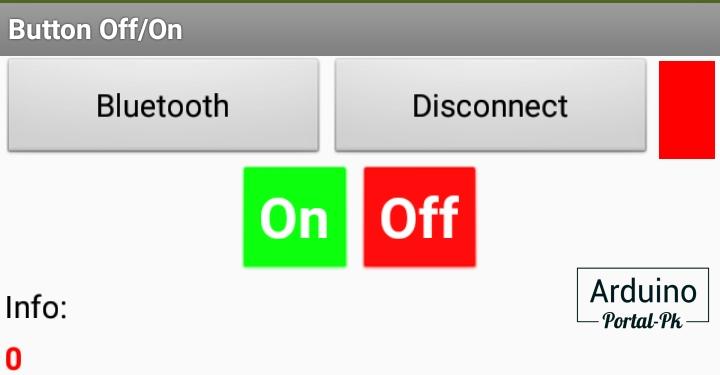
Интерфейс программы будет выглядеть вот так.
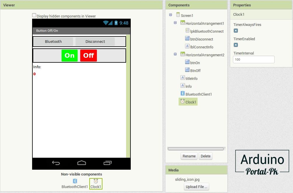
В приложение нужно добавить: BluetoothClient1 и Clock1 с интервалом обновления 100.
Кнопка «Bluetooth» осуществляет подключение к hc-06 модулю.
Копка «Disconnect» разрывает соединение.
Кнопки «On» и «Off» включают и выключают реле.
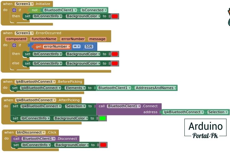
Блоки программы для подключения и отключения модулю HC-06 :
Блок управления и вывода информации на дисплей.
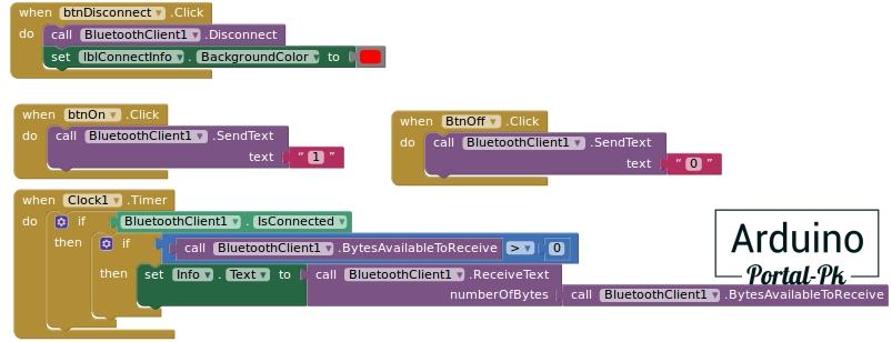
Копка включения отправляет по блютуз каналу значение равное 1. Кнопка отключения отправляет 0.
Cloc1 это часы, проверяют информацию которая пришла по Bluetooth и выводит ее в текстовое поле Info.
Приложение на Android устройстве выгладить вот так.
После нажатия на кнопку «Bluetooth». У вас откроется окно выбора устройства.
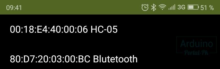
Выбираете ваше устройство. После чего можно управлять реле. При нажатии на кнопку «On».
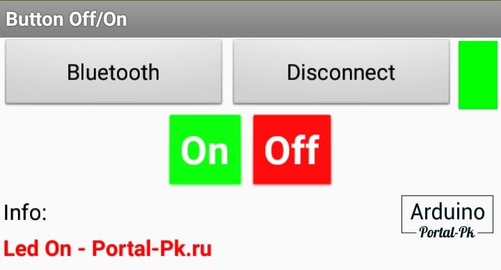
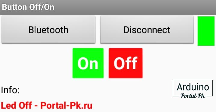
В поле Info выведется информация «Rele On — Portal-Pk.ru». При выключении реле на экран телефона будет строка «Rele Off — Portal-Pk.ru»
Подключаем к Arduino UNO реле и модуль по схеме. 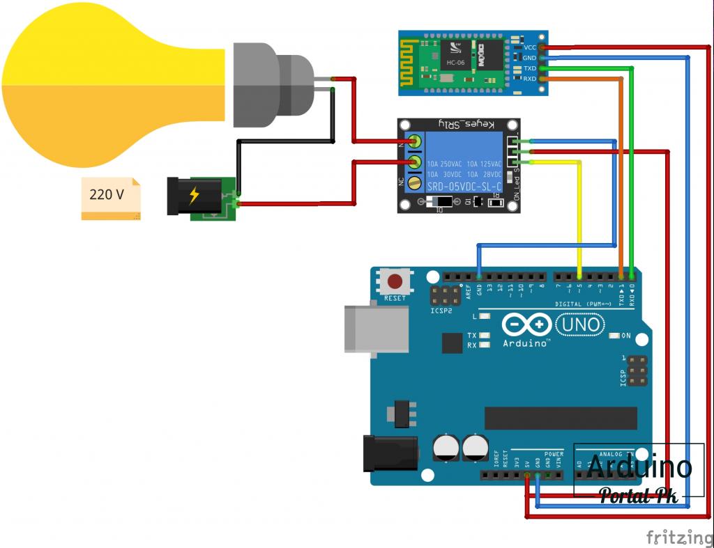
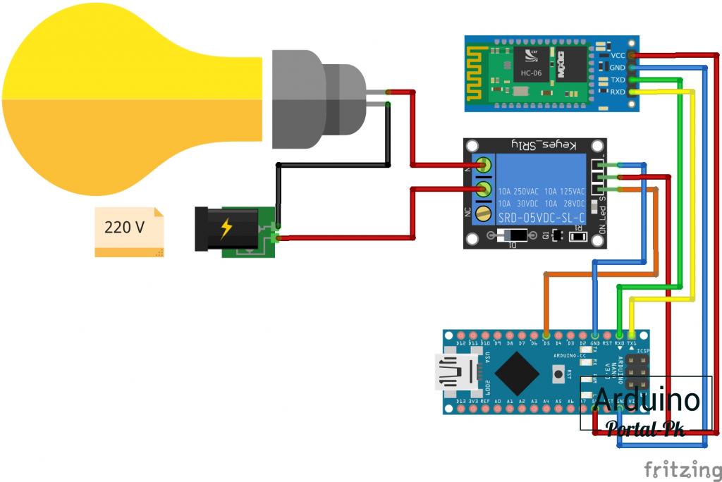
Если у вас Arduino NANO, то реле и bluetooth модуль hc 06 подключить по схеме.
Скетч bluetooth реле ардуино будет вот таким.
Если вы сделали все правильно, то у вас получиться вот такой результат.
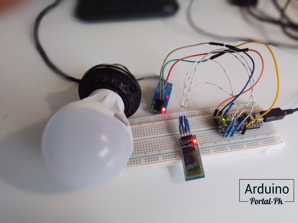
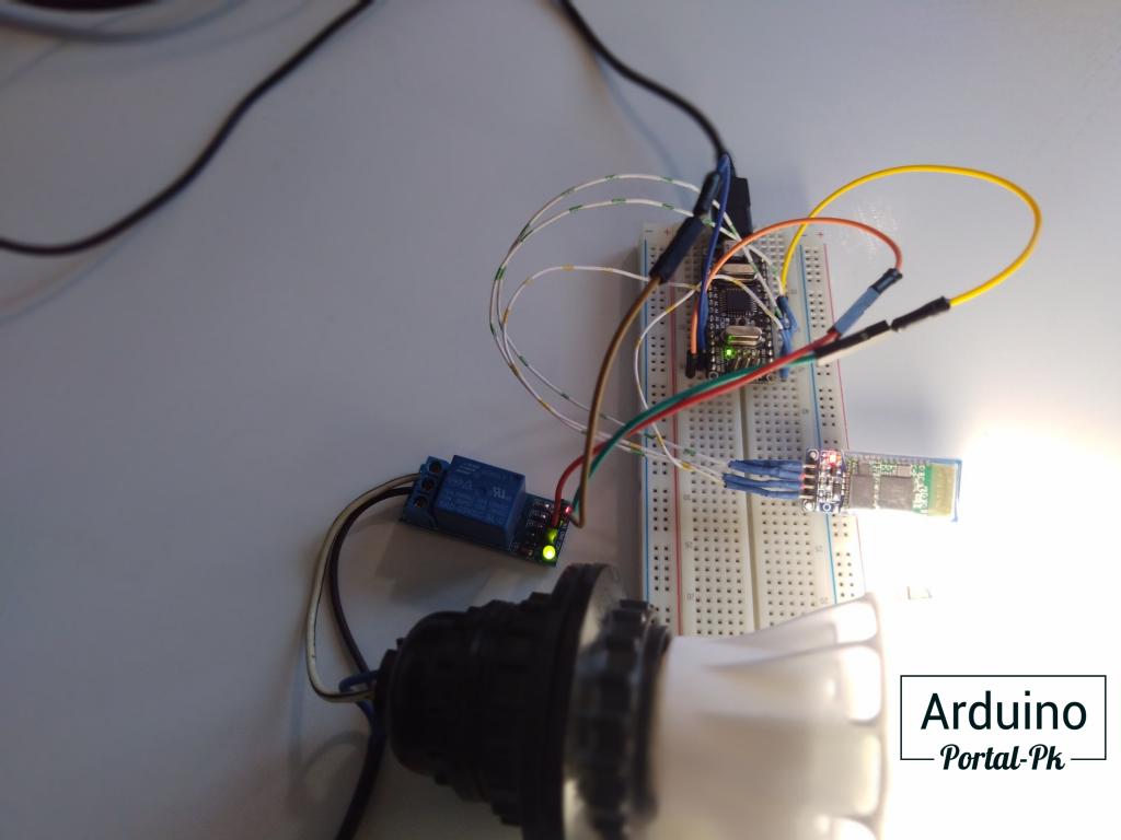
Подключенная нагрузка будет включаться и выключаться . Если у вас работает наоборот возьмите код для Arduino из урока: Bluetooth модуль HC-06. Управление Arduino с телефона.
Сегодня мы разобрали связку ардуино андроид bluetooth . Планирую сделать машину с управлением по bluetooth . И много другое.
Не забывайте подписываться на канал Youtube и вступайте в группы в Вконтакте и Facebook.
Всем Пока-Пока. И до встречи в следующем проекте.
Понравилась статья? Поделитесь ею с друзьями:
Источник
Martyn Currey
Mostly Arduino stuff
Create A Bluetooth Joypad With App Inventor 2
 Here we create a basic Classic Bluetooth joypad for use on an Android device to control a microprocessor (Arduino) connected to a Bluetooth module. The app is fairly simply. There are 2 screens; the first is the main control panel and the second is a connection page.
When the CONNECT button on the main screen is clicked the second screen is opened to allow the user to connect to a Bluetooth device. The direction buttons, when clicked, transmit codes to the Arduino.
App Inventor 2
The app is created in App Inventor 2 using Bluetooth Classic.
App inventor 2 is an easy way to get started with creating Android apps. It is designed primarily for teaching but you can build some surprisingly advanced and complex apps with it. App inventor is blocks based. This means programs are created using visual elements that are dragged and dropped rather than text that is typed. It is cloud based meaning you use a web browser.
I don’t go in to all the details of app inventor and I assume you have some basic experience with using it. At least you should have a google account and know where the app inventor website is.
Design
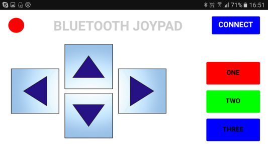
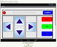
The Bluetooth Joypad has a simple interface and is used in landscape mode.
- 4 direction buttons,
- 3 regular buttons,
- a connection indicator, and
- a connect button.
When the CONNECT button is pressed a second screen will open. The second screen handles the Bluetooth connection and the update speed. 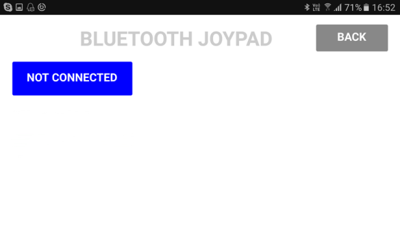
The second screen has;
- a button to initiate the Bluetooth connection process,
- a slider to control the app update speed,
- a BACK button to go back to the main screen.
As with many things in app inventor there are different ways to get the same layout. To make the layout as simple to create as possible I have a row across the top that holds the connection indicator and the menu button. Next there are 4 columns that hold the control buttons. Everything is then contained in an outer vertical arrangement which makes it easy to show/hide all the controls in one go. 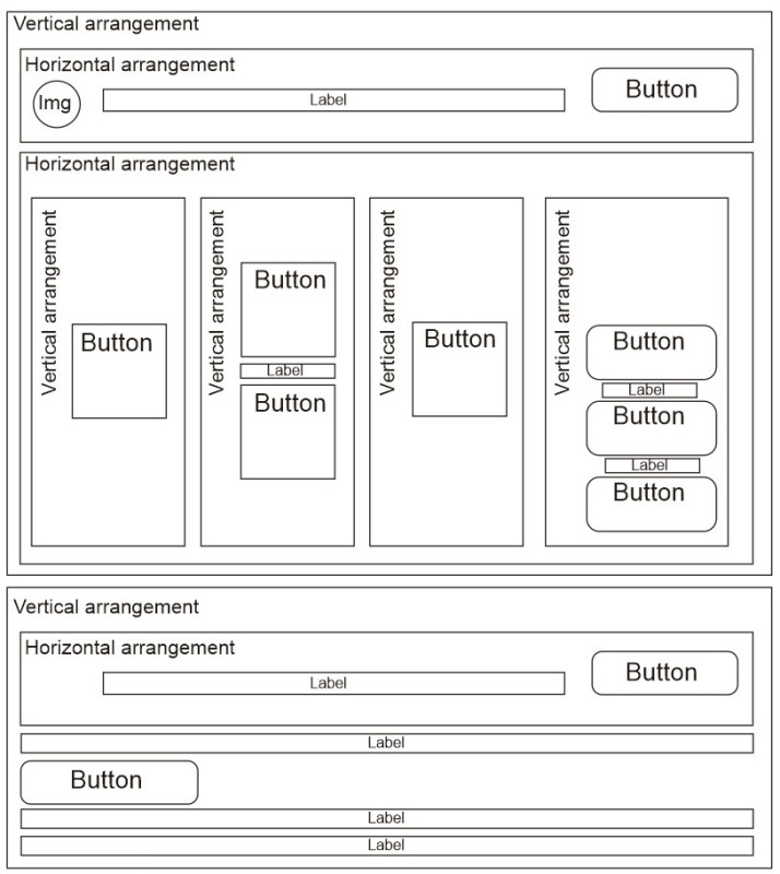
The first 3 vertical arrangements are vertically centre aligned.
The final column is bottom aligned.
The labels are used as spacers and aid the positioning.
Control codes
I am using single character control codes, this keeps the communication fairly simple and helps with the speed. Rather than using a single button clicked event I am using the button pressed and button released events. This means each button requires 2 codes:
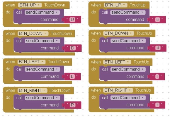
Direction Buttons
| U – Up button pressed | u – Up button released |
| D – Down button pressed | d – Down button released |
| L = Left button pressed | l – Left button released |
| R – Right button pressed | r – Right button release |
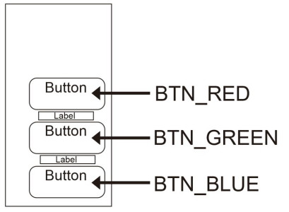
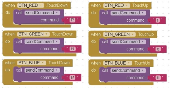
Control Buttons
| R – red button pressed | r – red button released |
| G – green button pressed | g – green button released |
| B – blue button pressed | b – blue button released |
The CONNECT button triggers internal events inside the app and does not need any code.
On the Arduino side, when it receives the character “U” it knows the up button has been pressed and when it gets the “u” character it knows the up button has been released. If it gets a “U” but no “u” it knows the up button is being held down. This is handy, for example, when using to control a remote car. “U” can mean go forward and keep going until the “u” is received. “R” can mean turn right, and keep turning right until the “r” is received.
Using single character codes also allows the Arduino code to be a lot simpler.
App Inventor 2 and Bluetooth
App inventor allows for apps with multiple screens but there is a caveat when using Bluetooth. Each screen has to have its own Bluetooth connection. This means if we use screen 2 to open a Bluetooth connection, after we go back to screen 1 we are no longer connected. To overcome this I will be using pseudo screens. The app will look like we are using 2 screens but in reality we are only using 1 and will be hiding and showing elements to make it look like we are swapping screens.
PAGE1_OUTER_VA acts as page 1 and PAGE2_OUTER_VA acts as page 2. When the app first starts only PAGE1_OUTER_VA is displayed. When the CONNECT button is clicked, PAGE1_OUTER_VA is hidden and PAGE2_OUTER_VA is displayed.
Screen Size
App inventor has some restrictions when it comes to screen size and how things are placed. It is good practice to use proportional sizing. This is where we specify the size as a percentage of the screen rather than by using resolution.
The direction buttons are about 18% of the screen width, the coloured buttons are 20%. You can change the sizes to suit your own design.
While developing the app I used a Samsung S7 but I also tried it on a Sony Compact Z3 and a Samsung 7” tablet. Although there are slight differences in the display on the 3 different devices the general layout is the same.
Creating the Layout
I do not go through every step of using App Inventor and expect that you have some experience with it. If not start by checking the online guides and examples. I do try to explain my choices and how best to handle things like Bluetooth.
Open a web browser and go to app inventor at http://ai2.appinventor.mit.edu/ and get started with a new project called Joypad_001. I append version numbers to the app name and as the app progresses I increase the value; Joypad_001, Joypad_002, etc.
The app screen is non-scrollable (I have found it better to leave the screen as scrollable and set it to non-scrollable in the code. Set the screen to Landscape and Responsive. Turn off the screen title by unchecking the TitleVisible check box.
Check Display hidden components in view
Then create the layout.
Start with the outer elements, set the correct alingment, and then create the inner elements like the buttons and labels.
Or, if you wish, download the layout aia file. This is the first stage only. It is a working app but it doesn’t do much. The CONNET button takes you to the second screen and the BACK button takes to back to the first one.
Notes about the layout
The Screen1 is centre aligned and PAGE1_OUTER_VA is set to 95% width. This means there is a small margin either side.
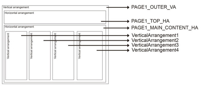
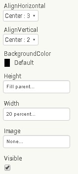 VerticalArrangement1,
VerticalArrangement2,
VerticalArrangement3
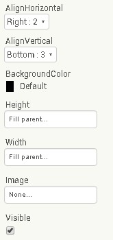 VerticalArrangement4
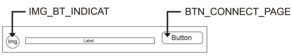
BTN_CONNECT_PAGE size: height 12% , width 18%.
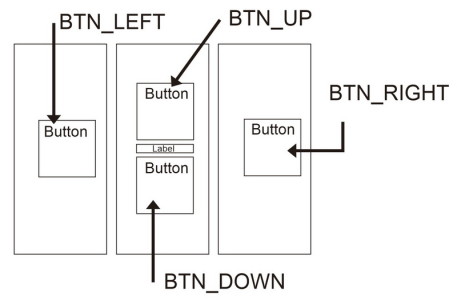
Direction buttons: height 30%, Width 18%.
Button size: height 15%, Width 20%.
Now add the images (right Click Save as) or download all images.


Once the layout is completed add some basic blocks so that you can see how the app will work: 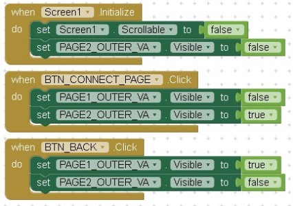
All these do is:
1. When the app starts (screen1.initialize)
– make the screen non-scrollable
– hide PAGE2_OUTER_VA
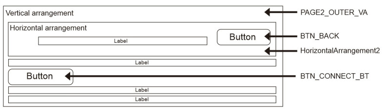
2. The next block handles the BTN_CONNECT_PAGE button. When the button is clicked page 2 is displayed;
– PAGE1_OUTER_VA is hidden (visible set to false)
– PAGE2_OUTER_VA is displayed (visible is set to true)
3. The third block handles the BTN_BACK. When this is clicked the app goes back to page 1 by hiding PAGE2_OUTER_VA and displaying PAGE1_OUTER_VA
Try what We have so far:
Download the BluetoothJoyPad_001 aia and give it a try.
Building The App
We will build the app in sections. In the first part we get the Bluetooth connecting and then we will add the button functions. Since the app will only have one way communication (app to Arduino) we do not need any code to handle receiving data, only sending. So all we need to do is make a connection, wait for a button press, and then send a code.
With Bluetooth Classic, the remote device has to be paired before we can make a connection. The pairing process is handled by the Android device via the devices settings. After a device is paired it remains in the Android devices paired device list. We will use this list in AI2 to allow the user to select the Bluetooth device to use. After the users selects a device the app will try to connect to it.
Since we are starting a new section, save the current project as “BluetoothJoyPad_002” and continue with the 002 version.
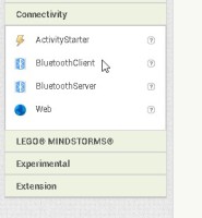
In the designer, add the Bluetooth Client to the project. In the Palette select BluetoothClient and drag it to the main window. This adds it to the project.
Now add a ListPicker to the very bottom of the layout. For TEXT enter “Bluetooth device list” and uncheck the Visible box. We will use the CONNECT button to activate the ListPicker. 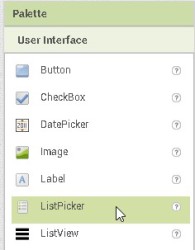

Next add a Notifier: 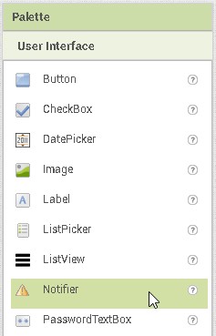
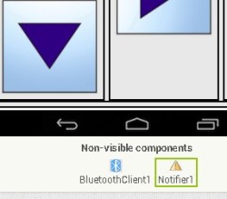
The Notifier will be used to display error messages, such as when Bluetooth is turn off or when a connection cannot be made.
In the Blocks editor, now that we have added the BluetoothClient we can access the Bluetooth blocks 
I won’t go in to the details of every step but I will show the blocks and try to explain what they do.
Bluetooth Connection
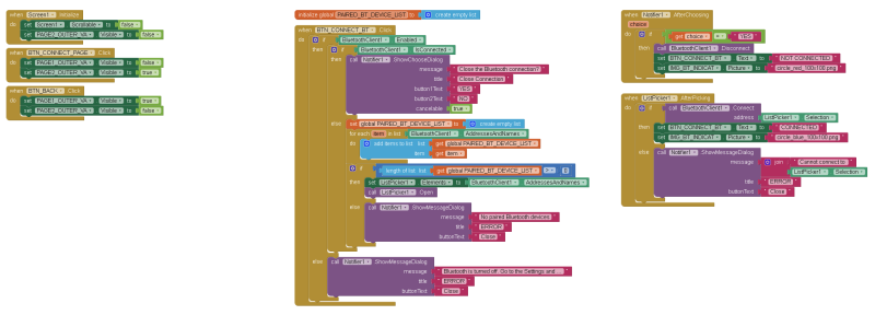
For the Bluetooth connection part we have 2 screen elements, the CONNECT button and the ListPicker. The ListPicker is set to invisible. There is also an empty list called PAIRED_BT_DEVICE_LIST. When the CONNECT button is clicked, the BTN_CONNECT_BT.Click function is called.
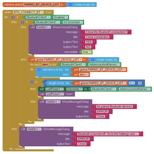
This first checks to see if Bluetooth is enabled. If not and error message is displayed. It then checks to see if there is already a connection, if there is, the user is asked if they would like to close it.
If Bluetooth is enabled and there isn’t a connection, all the paired devices are copied to the PAIRED_BT_DEVICE_LIST and if the length of the list > 0 we know we have at least 1 paired device and we can proceed. If the list is empty then another error message is displayed. If the list of paired devices is not empty, the list is then copied to the ListPicker and the ListPicker is activated. The paired device list comes from the system.
Using a list may seem like it is not required but it allows the app to check that there are paired devices. Without it there is the possibility that the app will display an empty list. Rather than showing the ListPicker on screen and allowing the user to click it, I use a button to activate it. This gives the app additional flexibility such as allowing the user to use the button to close the connection. This is a fairly robust way to initiate a connection in App Inventor 2.
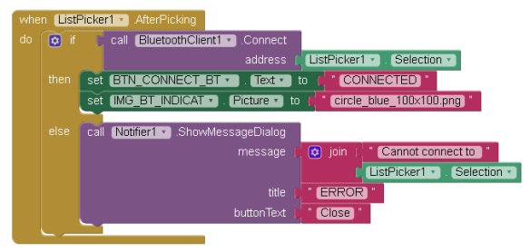
After the user selects once of the paired devices from the ListPicker, the ListPicker1.AfterPicking block is called. It is here we try to make the connection. 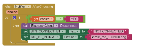
If the connection is successful, the image used for IMG_BT_INDICAT is changed to “circle_blue_100x100.png” and the text on the BT button is changed to “CONNECTED”. If the connection fails an error message is displayed.
If there is an active connection when the user clicks the CONNECT button they are asked if they would like to close the connection. The Notifier1.AfterChoosing handles the user response. If they click the YES button the connection is closed and the image used for IMG_BT_INDICAT is changed to “circle_red_100x100.png” and the text on the BT button is changed to “NOT CONNECTED”.
If you want to try this, set up an HC-06 or an HC-05 (no need for an Arduino) and on an Android device, use the Settings => Bluetooth to pair with the Bluetooth module. After that, run the App Inventor app and try to connect.
Now we have the connection part done we need to add the blocks to handle the button clicks.
Button Clicks
First, save the current project as “BluetoothJoyPad_003”.
As mentioned earlier, the button clicks will have 2 states, pressed and released. We achieve this is App Inventor2 with the Button.TouchDown and the Button.TouchUp blocks. 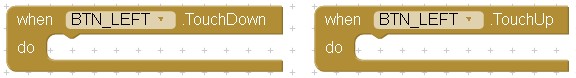
We will need both blocks for each button and each button will send a different command. We could simply send the command within these blocks but since we are going to check the connection status before sending it is better to create a separate procedure called sendCommand. 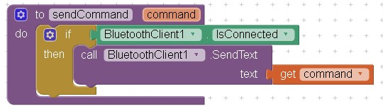
sendCommand receives the command to send, checks the connection status and if connected, sends the command. It is always a good idea to check the connection status before trying to send anything. When you try to send data and there is no active connection you get a system error and these quickly become very annoying.
Use the sendCommand procedure by calling it while passing the command (or text) to send: 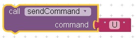
Now we can start to add the blocks to handle the button clicks. Remember that we are using capital letter for the TouchDown and lowercase for the TouchUp.
Arduino
Most of the app is done so we can start work on the Arduino side.
Since this article is about the joypad and not the Arduino I am using a very simple circuit and sketch to test the app. The circuit consists of an Arduino, a HC-06 Bluetooth module and a voltage divider. The app displays the received data in the serial monitor.
The Circuit
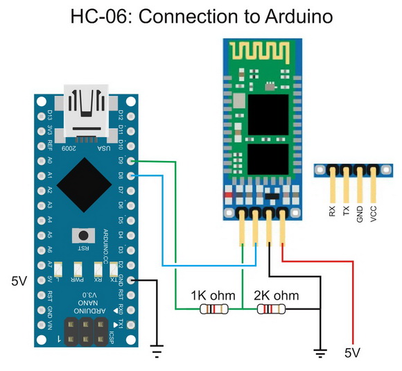

Arduino D9 (AltSoftSerial TX) to BT RX
Arduino D8 (AltSoftSerial RX)to BT TX
The BT module is getting power from the Arduinos 5V out pin
GND to GND.
The HC-06 RX pin is 3.3v and the Arduino D9 pin is 5V. This means we need to reduve the voltage. This is done with the voltage divider. The voltage divider uses a 1K ohm resistor and a 2k ohm resistor. This reduces 5v to 3.3v. The Arduino sees 3.3v as HIGH so we do not need to do anything on the BT TX pin. We can connect is directly to Arduino pin D8.
I am using a pre-made voltage divider.
The sketch is very simple. It uses AltSoftSerial to talk to the BT module and copies what ever it receives over AltSoftSerial to the serial monitor.
I am using a HC-06 and a HC-05 in slave mode can also be used. The HC-06 has the default settings:
Baud rate = 9600
Name = HC-06_ZG
// basicSerial_AltSoftSerial_01 // // Uses hardware serial to talk to the host computer and AltSoftSerial for communication with the bluetooth module // When data is received through AltSoftSerial it is copied to the serial monitor // // Pins // Arduino D8 (ASS RX) — BT TX no need voltage divider // Arduino D9 (ASS TX) — BT RX through a voltage divider // Arduino 5v out to BT vcc // GND to GND #include AltSoftSerial BTSerial; char c=’ ‘; void setup() < Serial.begin(9600); //Serial.print("Sketch: "); Serial.println(__FILE__); //Serial.print("Uploaded: "); Serial.println(__DATE__); Serial.println(" "); BTSerial.begin(9600); Serial.println("BTserial started at 9600"); >void loop() < // Read from the Bluetooth module and send to the Arduino Serial Monitor if (BTSerial.available()) < c = BTSerial.read(); Serial.println(c); >>
App In Action
Upload the code and run the app.

when the app opens, click the CONNECT button. This op[ens the connection page 
Hit the NOT CONNECTED button. 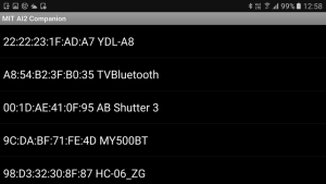
The list of paired devices is shown. Select the HC-06/HC-05 and the app tries to connect. 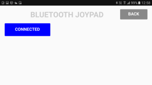
If a connection is successful the button text changes to CONNECTED. Hit the BACK button to return to the main screen. 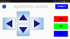
The connection indicator is now blue.
With the serial monitor open, click the direction buttons.If the world is being good to you you should see the control codes. 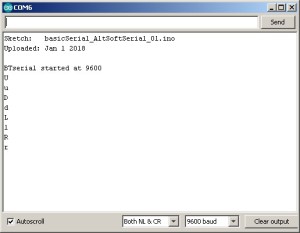
Now try the function buttons. 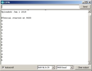
Things To Try Next
Change the function buttons so that they have a single pressed event rather than a pressed and released event. Use the button.Click block.
Add a connect code to the app. When a connection is made get the app to send “CONNECTED” to the Arduino. You can then use this to know a connection has been established.
Downloads
7 thoughts on “ Create A Bluetooth Joypad With App Inventor 2 ”
hallo my teacher i,m from indonesia, want to learn arduino.make the temperature and relay project which monitor from android, thanks teacher
Thankyou for this tutorial. This is very helpful to me. But i wand to send “z” when no any button is clicked. for example if up button is clicked send “A” if not clicked send “z”. How can i get this?
C’est vraiment excellent votre site.
Bon continuation…..
Hello exceptional site and clear even for a pensioner like I am. And I wanted to ask you but what firmware can I use? Thanks bye
which firmware are you referring to?
Hi I was too optimistic but with what sketch it works. Thanks
There is a basic sketch above to show the app working, beyond this it is up to you to create your own sketch to make use of the app.
Источник