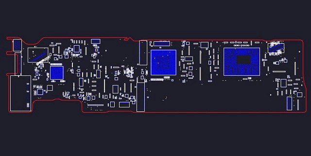
Скачать бордвью Macbook Pro Retina 15″ A1398 820-3332-A BoardView. Мы верим в возрождение технологии и минимизацию электронных отходов, поскольку наша…
MacBook Air 11″ A1465 820-3435-B BoardView
Скачать бордвью MacBook Air 11″ A1465 820-3435-B BoardView. Мы верим в возрождение технологии и минимизацию электронных отходов, поскольку наша область…
Macbook Air 13″ A1466 820-3437 BoardView
Скачать бордвью Macbook Air 13″ A1466 820-3437 BoardView. Мы верим в возрождение технологии и минимизацию электронных отходов, поскольку наша область…
Macbook Air 13″ A1466 820-3437-B BoardView
Скачать бордвью Macbook Air 13″ A1466 820-3437-B BoardView. Мы верим в возрождение технологии и минимизацию электронных отходов, поскольку наша область…
MacBook Pro A1425 Retina 820-3462-A BoardView
Скачать бордвью MacBook Pro A1425 Retina 820-3462-A BoardView. Мы верим в возрождение технологии и минимизацию электронных отходов, поскольку наша область…
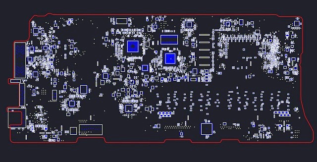
MacBook Pro Retina 13″ 820-4924 820-3476-A BoardView
Скачать бордвью MacBook Pro Retina 13″ 820-4924 820-3476-A BoardView. Мы верим в возрождение технологии и минимизацию электронных отходов, поскольку наша…
Macbook Air 13″ A1466 820-3437-A BoardView
Скачать бордвью Macbook Air 13″ A1466 820-3437-A BoardView. Мы верим в возрождение технологии и минимизацию электронных отходов, поскольку наша область…
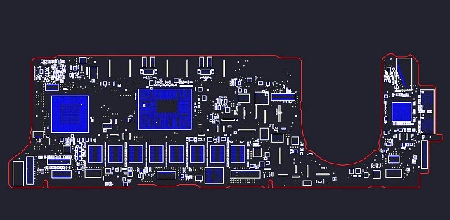
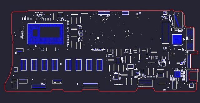
A1502 820-3536_ 820-3536-A_ 820-3536-B BoardView
Скачать бордвью A1502 820-3536_ 820-3536-A_ 820-3536-B BoardView. Мы верим в возрождение технологии и минимизацию электронных отходов, поскольку наша область —…
MacBook Air A1304 820-2375 BoardView
Скачать бордвью MacBook Air A1304 820-2375 BoardView. Мы верим в возрождение технологии и минимизацию электронных отходов, поскольку наша область —…
Macbook Pro A1278 820-2530 BoardView
Скачать бордвью Macbook Pro A1278 820-2530 BoardView. Мы верим в возрождение технологии и минимизацию электронных отходов, поскольку наша область —…
Страниц для загрузки больше нет
Топ спонсоров
350 руб. АлартМастер — Ремонт компьютеров Спасибо большое! Помогли найти Биос на клиентский ноут.
213 руб. ИП Салимов А.Ю Везде платно, а здесь постоянно скачиваю бесплатно. Заезжайте на ремонт сделаю скидку
Telegram chat + file archive Bios, Schematic, Boardview for Laptop | PC Unlimited downloads On request, add any file for laptops with devicedb.xyz and other Demo access 1$ — 1 Day | For all questions, write https://t.me/DeviceDB_xyz
DeviceDB 3
Промокоды для РФ и стран СНГ ALIDIDI2 — скидка 250/1250 руб. SEKRET150 — скидка 150/1000 руб. SEKRET300 — скидка 300/2300 руб. SEKRET500 — скидка 500/3800 руб. SEKRET700 — скидка 700/5300 руб. SEKRET900 — скидка 900/6700 руб. SECRET1300 — скидка 1300/10000 руб. SEKRET1600 — скидка 1600/12000 руб. SECRET1950 — скидка 1950/15000 руб. SECRET2600 — скидка 2600/20000 руб.
100NEWYEAR скидка — 100/1000 руб. 2500NEWYEAR скидка — 250/2500 руб. 500NEWYEAR скидка — 500/5500 руб. NEWYEAR700 скидка — 700/7700 руб. NEWYEAR1000 скидка — 1000/11000 руб. NEWYEAR1300 скидка — 1300/15000 руб. NEWYEAR1700 скидка — 1700/20000 руб. NEWYEAR4000 скидка — 4000/45000 руб. NEWYEAR5300 скидка — 5300/60000 руб. NEWYEAR6300 скидка — 6300/70000 руб.
Промокоды для Украины и Европы GIFT2n скидка — $2 от $15 GIFT6n скидка — $6 от $45 GIFT10n скидка — $10 от $80
DeviceDB 3
hygge100allnov предоставляет скидку на 100 от 1000 рублей
hygge200allnov предоставляет скидку на 200 от 2000 рублей
ITSFRIDAY20 — скидка 20₽ от 150₽
ITSFRIDAY70 — скидка 70₽ от 500₽
ITSFRIDAY100 — скидка 100₽ от 700₽
ITSFRIDAY200 — скидка 200₽ от 1500₽
ITSFRIDAY300 — скидка 300₽ от 2500₽
ITSFRIDAY400 — скидка 400₽ от 3500₽
ITSFRIDAY700 — скидка 700₽ от 7000₽
ITSFRIDAY1000 — 1000₽ от 10500₽
ITSFRIDAY1200 — 1200₽ от 14000₽
ITSFRIDAY1500 — 1500₽ от 17900₽
ITSFRIDAY2100 — 2100₽ от 22000₽
ITSFRIDAY3000 — 3000₽ от 35000₽
ITSFRIDAY4000 — 4000₽ от 43500₽
ITSFRIDAY5300 — 5300₽ от 57500₽
ITSFRIDAY6300 — 6300₽ от 73000₽
ITSFRIDAY7500 — 7500₽ от 80000₽
Для других стран, помимо СНГ:
LOVEBF22 — 22$ от 200$
LOVEBF33 — 33$ от 300$
LOVEBF44 — 44$ от 400$
LOVEBF55 — 55$ от 500$
Источник
Схемы iPhone и iPad [Скачать PDF]
Не так давно я написал статью о замене контроллеров питания и зарядки iPhone (ссылка на статью), в которой простым языком объяснил пользователям с чем им приходится иметь дело, если телефон не включается или не принимает заряд.
Для более детального понимания вопроса мне пришлось хорошо покопаться в интернете и пересмотреть не один десяток видео по ремонту техники Apple.
Так вот, в процессе поиска информации, я с трудом смог найти принципиальные схемы iPhone и iPad, которые были необходимы для определения положения микросхем на платах.
Для чего бы вам не потребовались схемы iPhone и iPad, скачивайте их по ссылкам.
Схемы iPhone
Я нашел всего два места где их выложили для свободного скачивания, и много мест где за это просили деньги, поэтому решил исправить ситуацию и поделиться схемами плат со своими читателями.
iPhone 2GS — Скачать
iPhone 3GS — Скачать
iPhone 4 — Скачать
iPhone 4S — Скачать
iPhone 5 — Скачать
iPhone 5C — Скачать
iPhone 5S — Скачать
iPhone 6 / 6 Plus — Скачать
iPhone 6S / 6S Plus — Скачать
iPhone 7 / 7 Plus — Скачать
Схемы iPad
Все схемы представлены или в PDF формате, или запакованы в RAR архив (где кроме схем есть еще много полезной информации по распиновке, а также фотографии реальных плат iPhone).
Кстати, все принципиальные схемы техники Apple являются интеллектуальной собственностью компании Apple и не подлежат свободному распространению. Никто не имеет права их копировать или частично воспроизводить в каком либо виде.
Никому их не показывайте их нигде не публикуйте. Я в свою очередь, со страниц этого сайта только ссылаюсь на хранилище Yandex Disk.
Источник
iPhone 7
Models
Model
Type
Modem
Region
A1660
7
Qualcomm
Global
A1778
7
Intel
Global
A1779
7
Intel
Japan
A1780
7
China
A1661
7+
Qualcomm
Global
A1784
7+
Intel
Global
A1785
7+
Intel
Japan
A1786
7+
China
Problem
Solution
No Power — Pulls ≈2 A or more before you prompt to boot on DC power supply
Do a full visual inspection of the board and check for water damage under the stickers on the back. Remove the foam around the connectors to get a better look at everything. You’re looking for any signs of corrosion on or around components and ICs.
If there is no water damage, is is most likely a shorted capacitor on any of the below lines:
PP_VDD_MAIN — This is the most likely line to be shorted
PP_VDD_BOOST — This line is usually shorted when it’s not VDD MAIN
PP_LCM_BL_ANODE or PP_LCM_BL34_ANODE — Sometimes the backlight circuit has a short and causes the same symptoms
PP_SPKR1_VBOOST — This is a bit rare but it does happen
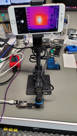
You’ll need to inject voltage (4 V / 2 A) directly into the line you measured as short and use freeze spray (see here https://youtu.be/3MtLSQJvQxI) or thermal camera (see here: https://youtu.be/fkd4iDjgfvc) to spot the capacitor that is shorted.
In these cases, you can just remove the shorted capacitor and not replace it. The device will function normally with no negative effects.
Replacing it means you are adding more heat to the board to reinstall it, which increases the risk of something going wrong.
If you have a case of water damage, then you’ll have to pay attention to the spots on the board where there’s signs of water damage.
Often, you’ll find corrosion on capacitors but also under ICs.
Common ICs and areas to have corrosion and cause a VDD MAIN short:
Under BBPMU_RF and around it, like Capacitors: C5625_RF, C5622_RF
Back top «arm», like C2611, C2612, C2609, C2610
Back bottom, like the backlight caps C3725, C3705, C4602, C4612
Above and next to WiFi (WLAN_RF), like C7610_RF, C2527, C3002
Front Top above CPU, like C3327, C3328, C3313
You’ll need to visually inspect these areas to see if they’re liquid damaged
Please Note: If you are using a DC power supply to inject voltage through the battery connector, like using an iPower Pro or DT880 (see here https://youtu.be/rawjB9yxe1A), be aware that the Tigris Mosfet Q2101 will heat up instantly. This is because the battery connector line PP_BATT_VCC connects to PP_VDD_MAIN through it, which creates lots of heat. Q2101 itself does not have a connection to ground, therefore, it’s impossible for it to be shorted.
No Power — Hangs at 0.020–0.030 A after you prompt to boot on DC Power Supply
Symptoms: [ edit | edit source ]
No Power/Doesn’t boot. Just dead.
Cannot get into DFU mode.
When the board is connected to a DC power supply
You get 0 A draw before prompt to boot
When you prompt to boot, it jumps up to 20–40 mA and just hangs at that value. No fluctuation
Solution: [ edit | edit source ]
Clean underfill above CPU
Clear out all underfill around L1801, L1804 and L3302
Poke those coils and see if they break off
If any of the three break, replace the coils that broke off.
Coil values
L1801 — 1 μH, 2.1 A, 0.12 Ω
L1804 — 1 μH, 2.1 A, 0.12 Ω
L3302 — 1.2 μH, 3.0 A, 0.080 Ω
Please Note: You cannot check for these coils if they’re loose by poking them with the underfill still there. You MUST clear it all out around these coils and then poke them to see if they break off.
Also, these are pressed up right against the CPU, so be careful with your hot air, because you can accidentally «float» the CPU and cause a more significant failure.
No Power — After prompt to boot on DC power supply, current jumps back and forth from 0 A to 320 mA, then 0 A to 1.4 A, then 0 A to 500 mA, and so on
Symptoms: [ edit | edit source ]
No current draw before prompt to boot on DC power supply
After prompt to boot, you see the current jump quickly between 0 A and various values, like 0 A > 320 mA > 0 A > 1.4 A > 0 A > 500 mA
Solution: [ edit | edit source ]
Check for shorts around NAND
Usually you’ll find these lines with a shorted capacitor:
PP3V0_NAND
PP0V9_NAND
If so, find the shorted capacitor by injecting voltage
Please note: PMIC (U1801) will often show lots of heat if you’re testing with the DCPS connected through the battery connector but it’s not the cause of the short. The short is at the capacitor next to NAND, but since you’re connected to the battery connector, the current has to flow through PMIC to get to the short cap, hence the PMIC heats up.
Another Possible Cause: [ edit | edit source ]
Sometimes, you’ll see this same behavior when PP1V8_SDRAM or PP1V1_SDRAM is shorted. If this is the case, you’ll need to check for heat above the CPU. If you find PP1V8_SDRAM or PP1V1_SDRAM is shorted and find heat above the CPU, then it’s a RAM short.
You’ll need to replace RAM to solve it. This a very advanced repair and should only be done by those who’ve mastered this repair. It’s very easy for things to go wrong and damage the CPU.
Not Charging — Turns on but doesn’t charge. Takes ≈0.006 A via USB power meter.
There are multiple ways to test and diagnose a charging issue/Tristar failure
Diagnosing [ edit | edit source ]
Step 1: Rule Out Parts Issues [ edit | edit source ]
Test the logic board with known good parts, like a known good charging port flex and battery.
These are parts that you have previously tested and confirmed they’re good. Sometimes using just new stock is not enough, because sometimes new stock is defective.
Ideally, take the board out of the housing and only plug in a screen, battery and charging port to the logic board, then plug it in to charge and check the USB meter.
This helps remove all variables, as sometimes, a bad flex can cause charging issues; rare, but it happens.
If the current is still around 0.006 A via your USB meter, the phone turns on, but does not show charging symbol, then it’s a board issue.
Generally, these scenarios are Tristar — U4001 — Part# 610A3B.
You can use a tool called «Tristar Tester», which generally works well with detecting a bad Tristar, although it’s not foolproof.
These two are the most popular on the market
Smartmod Pro Tristar Tester
ICC Pro Tristar Tester
Both scan for charging port issue, then Tristar issue.
If either say «Tristar Fail», it’s a super high chance it’s Tristar (see video at 4:21 https://youtu.be/KAMpmxeaNys?t=261)
Although, a «Tristar Pass» can still be a bad Tristar.
Use this as one of your clues to a bad Tristar, but don’t trust it to be 100% accurate.
In either case, you can continue the diagnosis process to help further confirm a Tristar issue
Step 3: DC Power Supply Boot Up Consumption [ edit | edit source ]
With a DC power supply or DT880, see what is the power consumption before and after prompt to boot.
If you get current draw before prompt to boot, then it’s not Tristar. See above Problem/Solution, as it will be a short on the board.
If you don’t get current draw before prompt to boot, but after you prompt to boot, the first number of the current draw of the boot sequence is ≈0.150–0.250 A, then it definitely points towards a bad Tristar (see video at 6:39 https://youtu.be/KAMpmxeaNys?t=399).
You can also use a thermal camera or freeze spray to check if Tristar heats up when you prompt to boot. Usually it will get hot when it’s bad, but not always.
Step 5: Check Voltage at the Battery Connector [ edit | edit source ]
Plug in the charging port flex to the logic board, and nothing else. No screen, no battery, etc.
Then plug in the charging cable to the charging port.
Set your multimeter to DC volts mode, and measure the positive and negative battery pins of the battery connector J2201.
These are the 2 large pins on each side.
Polarity for this test doesn’t matter, just ignore the negative symbol if you end up probing in reverse polarity
If the voltage is lower than around 2 V, then Tristar is bad. Usually around 0.300–0.600 V
A working charging circuit will show about 3.7 V
Solution: [ edit | edit source ]
Replace Tristar [ edit | edit source ]
After all these tests, you can replace Tristar and see if it’s solved.
Tristar for iPhone 7 and 7 Plus requires the version 610A3B. Please make sure to use the correct version, as previous iPhone models use slightly different versions of Tristar.
Please Note: Tristar on iPhone 7 and 7 Plus is partially covered by a shield. It is highly recommended that you don’t touch the shield. You should be able to pull off the chip at an angle and place the new Tristar at angle. (See video at 13:22: https://youtu.be/KAMpmxeaNys?t=802)
Cutting the shield to get full access to Tristar will risk damaging surrounding components. Also, cutting the shield creates sharp points on the shield, which tend to stick out. This will cause the shield to cut or pierce through the charging port when you put it back into the housing, which will cause No Charging again.
After Replacing Tristar [ edit | edit source ]
Once you replace Tristar, you can follow the same steps from above to confirm if it’s solved.
Check USB Charging with just your known good screen, battery, and port. It should be what a known good charging iPhone looks like. Generally 1 A or more.
Run the Tristar Tester tool again (if you have one) and see if it passes now
Check the first number after you prompt to boot. It should be around ≈0.045 A
Check if Tristar still heats up with freeze spray or thermal camera
Check if the voltage at the battery connector is at 3.7 V, per Step 5 above
You’ll want to compare you previous results to the new results. This tells you if the issue was solved or there’s a problem still present on the board.
Please note: Each charging brick is slightly different, so it is recommended to get familiar with your charging brick and cable. Each cable and brick will give slightly different USB charging current readings based on the specs of the current output. You can read the charging brick itself to see the specs.
You can get a known good iPhone of the same model and see what the USB charging current is, then compare to the device you are repairing to see if it’s about the same.
Also, batteries that are close to a full charge will charge at a lower current than a low battery. Old/worn out batteries also charge at lower rates, as they’re degraded and can’t take as much current.
Other Possible Charging Faults [ edit | edit source ]
If it still doesn’t charge after replacing Tristar, make sure you followed all the troubleshooting issues above.
Then, you’ll want to check for shorts around Tristar.
You can probe both sides of each capacitor that’s directly surrounding Tristar and check for continuity to ground.
It’s possible that TRISTAR_BYPASS capacitor C4005 is shorted to ground. It is recommended to replace.
C4005 value: 1.0 μF, 6.3 V, 0201 package
You can also remove Tristar and diode mode all the Tristar pads.
Compare the readings on your boardview software, like ZXW to your board.
You can also compare diode mode readings to a known good board.
If you find any shorts, you’ll need to inject voltage to find the shorted capacitor.
Audio IC Issue — Grayed out speaker button during a call
Voice Memo app doesn’t record
No sound in certain apps
Mic doesn’t work for Siri
Lightning to 3.5 mm headphone jack doesn’t work
Lightning headphones don’t work
Some people also call this «Audio Disease»
On older iOS versions, the device will get stuck on Apple logo for ≈7 minutes but then boot up fine and work, but experience audio issues.
Diagnosing [ edit | edit source ]
These are the two of the best steps to diagnose the Audio IC failure.
1. Make a call [ edit | edit source ]
If the phone has been experiencing audio issues and you have a supported SIM card available, the first thing to do is make a call and see if the speaker button is grayed out.
Calling 611 is the easiest option, as it is the universal phone number for the carrier’s customer service. This will allow you to test the speakers, as there is a recorded voice on the other end of the call.
Usually, the speaker button will be grayed out if the Audio IC issue is present.
Sometimes, the speaker icon won’t be grayed out, but there will be no audio out the ear speaker.
Or sometimes the speaker icon can be enabled, but just turns off within seconds. You turn it back on and it turns off again.
Please Note: Bluetooth audio, including AirPods, will still work fine when an iPhone 7 or 7 Plus has Audio IC issue present.
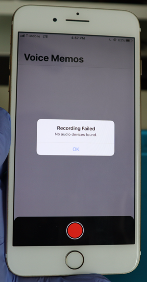
2. Voice Memo App [ edit | edit source ]
If you don’t have a supported SIM card available, you can also use the Voice Memo app.
Depending on iOS version, you will have different symptoms here.
iOS 11 and older, the voice memo app will have a grayed out record button
iOS 12 will show «Recording Failed, No audio devices found» pop up when you click record.
iOS 13 and 14 will allow you to click the record button, but nothing happens. No recording starts. (See video at 0:28 https://youtu.be/IoGEWsZtOiE?t=28) (Also see iOS 12 vs iOS 13 behaviors here: https://www.instagram.com/p/B3IUb6qnm4T/)
Sometimes, the voice memo app will allow you to record, even though the user has experience intermittent audio issues.
In these cases, you can start recording a voice memo, while at the same time, gently twisting the frame for 5–10 seconds. Then playback the recording
If Audio IC issue is present, you’ll hear the playback audio with distortions and abnormal sounds.
Solution [ edit | edit source ]
Warning: Attempting this repair without enough experience with microsoldering, may lead the a «Baseband» issue, where you have «No Service» or non-stop «Searching. » issue. Proceed with caution.
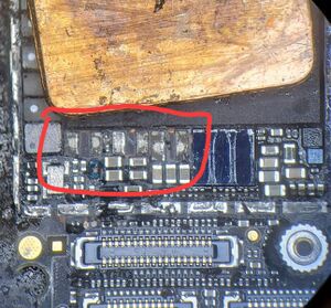
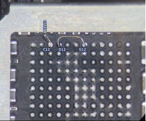
Reball Audio IC U3101 and add C12 and D12 Jumpers [ edit | edit source ]
The reason why the Audio IC issue occurs is due to the C12 and sometimes the D12 pads under the IC will break. Both of these pads are critical for the audio function of the phone to work. If either of these pads are broken or loose, you’ll get the symptoms mentioned above.
Making these 2 jumpers are critical to permanently solving the Audio IC issue, regardless if the pads break during IC removal or prepping the pads with your iron. Do not skip this step.
Sometimes, you’ll run into a case where H12 and/or J12 will also break when removing the IC or prepping the pads, but these two pads do not cause the symptoms described above. If either of these two break, it would cause no audio through the lightning port, like using headphones through a lightning to 3.5 mm headphone jack adapter.
Adding jumpers for H12 and J12 is optional.
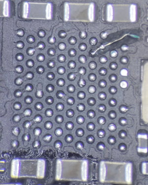
Making The Jumpers Under Audio IC U3101 [ edit | edit source ]
C12 [ edit | edit source ]
Scratch out the trace that goes from C12 to R1103.
Zoom in close enough to see the trace and use a blade to gently scratch out that trade.
Then tin the trace
Install jumper wire
Add UV Mask to hold the jumper in place.
See video at 20:35: https://youtu.be/jr5lvCFTgoo?t=1235
The C12 pad may or may not break off, but the jumper wire must take up the space where the C12 pad would sit, to ensure the solder ball on the IC makes contact with the wire.
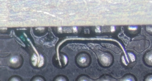
Some people prefer to keep the wire straight across like in the example image here
Some people prefer to curl the end of the wire so it makes a «J» shape or coiled shape.
In either case, it will work.
D12 [ edit | edit source ]
D12 is a bit rare to break off, but it does happen, so it is recommended to jump this to avoid any warranty issues in the future
There are many places you can jump D12 to, but the most practical being to jump to G12
You can achieve this by make the jumper in the shape of a staple, by attaching the jumper to the pad, go up, then 90° to the right, then 90° down to G12
Make sure to give a lot of clearance and not have the jumper wire to close to the surrounding pads
Make sure to not let the jumper wire touch the components above it either.
No need to scratch out any traces in this case.
Add UV Mask towards the top of the jumper wire. This will hold the jumper in place
See video at 12:14: https://youtu.be/IoGEWsZtOiE?t=734
The final result should look something like this:
Other Jumpers [ edit | edit source ]
If F12, H12, J12 or any other pads rip, follow the path of each pad and solder the wire to that component
F12 should run a jumper to C3220
H12 should run a jumper to R3103
J12 should run a jumper to R3104
The Audio IC Chip — Reuse or Replace? [ edit | edit source ]
Please note: The root cause of the Audio IC issue is not caused by a bad Audio IC chip, so replacing it is not required. You can reuse the same IC by reballing the IC and placing it back once the jumpers are installed.
Sometimes, the IC gets damaged during removal and you will experience these issues:
Voice Memo App will record just fine and play back fine
Speaker button is not grayed out and working, but only bottom loudspeaker works. If you turn off speaker mode, the ear speaker will have no sound.
In this case, replace the IC and that should solve the no ear speaker sound after Audio IC repair attempt.
If you experience No Power or Overheating, then try removing the IC and test again.
Be aware that the phone will boot without the Audio IC installed. So if the phone boots up without the Audio IC installed and doesn’t overheat, then this confirms the Audio IC chip itself went bad somewhere in the process.
Replace the Audio IC in this case.
Underfilled Audio IC [ edit | edit source ]
If you come across an Audio IC that is underfilled, it is recommended you just replace the IC, as it will be difficult to reball the original and most likely damaged during removal.
An underfilled IC is one that has black «glue» holding down the IC. It is believe that Apple started doing this on certain batches to help cover up the widespread Audio IC Issue.
You see the whole process of removing the Underfilled Audio IC here: https://www.youtube.com/watch?v=jr5lvCFTgoo
Final Testing [ edit | edit source ]
Test Voice Memo App and make sure the app is recording your voice.
Play back the audio recording and verify you get sound out of both the ear speaker and bottom loud speaker.
iPhone 7 and 7 Plus has stereo sound, so the ear speaker and bottom speaker will play sound of them at the same time when playing back any Voice Memo recording.
If you notice the ear speaker sound has static/distortion, check the ear speaker mesh. If it’s dirty, it will cause this issue.
Clean out the ear speaker mesh to solve it
Make a phone call and verify the ear speaker has sound and make sure the loud speaker has sound.
If all tests look good, then the issue is solved.
Stuck in «Searching» or «No Service» after Audio IC Repair attempt
Baseband Issue after Audio IC
Symptoms: [ edit | edit source ]
After an Audio IC Repair was attempted, you see this:
With no SIM Card installed, the phone is always «Searching. » or «No Service».
A working phone will show «No SIM» with no SIM Card installed.
Dial *#06# in the phone app, and nothing happens
A working phone with no Baseband issue, will make the IMEI pop up.
If you go to Settings > General > About > Model Firmware is blank
Cause: [ edit | edit source ]
When too much heat is used when attempting to removed Audio IC or placing it back, the Baseband CPU (BBCPU) on the opposite end, which is underfilled, will disconnect (or float) and cause these problems
(In addition) if you’re so sure of your skill on audio IC and you get no service after audio IC, before moving to baseband CPU, first reflow or reball baseband PMU, this is common too.
Solution: [ edit | edit source ]
This will require you to reball baseband CPU (BBCPU). This process is a bit risky due to CPU being right next to BBCPU and the potential of floating the main CPU is very high. It is recommended to not risk attempting this repair if you don’t have enough experience working with underfilled chips and working next to CPU.
Here’s a video of the whole process: https://youtu.be/JP3ghPMjuR0
Please note: If you attempt the above repair, but it’s still stuck in «Searching. » or «No Service», then flash an update (DO NOT RESTORE). This can sometimes solve the issue. Not sure why it is needed sometimes.
If a phone with a baseband problem is restored, then the iOS software will «erase» the IMEI (baseband info) in the phone and will require the board issue to be fixed, then restored again, so the software will bring back the IMEI.
If you restore, and still has no IMEI, then a baseband/board issue is still present on the board. That will need to be fixed, then restored again.
Developed the issue with the phone stuck in «Searching» or «No Service» on its own (no previous repair attempts)
Symptoms: [ edit | edit source ]
If no previous repairs attempts were made on the phone, but has these symptoms:
With no SIM Card installed, the phone is always «Searching. » or «No Service».
A working phone will show «No SIM» with no SIM Card installed.
Dial *#06# in the phone app, and nothing happens
A working phone with no Baseband issue, will make the IMEI pop up.
If you go to Settings > General > About > Model Firmware is blank
Cause: [ edit | edit source ]
Intel Model [ edit | edit source ]
BBPMU_RF (Baseband Power Management Chip) has failed and just needs to be replaced
Qualcomm Model [ edit | edit source ]
Ground pads under BBPMU_RF have broken
Or there’s a short on the Transceivers chips (XCVR1_RF and XCVR0_RF)
Or BBCPU is internally shorted
Solutions: [ edit | edit source ]
Intel Model [ edit | edit source ]
Replacing BBPMU_RF should solve it.
Part# 6826
Qualcomm Model [ edit | edit source ]
Check for shorts around BBPMU. Probe all large caps around the chip for any shorts.
If no short, pull BBPMU, run jumpers for the corner ground pads, 98, 93, 88, 83 and attach to ground layer of the board. (Example pic coming soon)
To be safe, just replace the chip, vs reballing, as the chip could be bad.
Please note: If you attempt the above repairs, but it’s still stuck in «Searching. » or «No Service», then flash an update (DO NOT RESTORE). This can sometimes solve the issue. Not sure why it is needed sometimes.
If a phone with a baseband problem is restored, then the iOS software will «erase» the IMEI (baseband info) in the phone and will require the board issue to be fixed, then restored again, so the software will bring back the IMEI.
If you restore, and still has no IMEI, then a baseband/board issue is still present on the board. That will need to be fixed, then restored again.
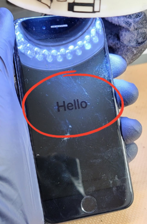
Symptoms [ edit | edit source ]
If a phone has been restored and stuck at the Hello screen
You try to activate and get the «Unable To Activate» screen
Solution [ edit | edit source ]
There are 2 potential causes
Baseband issue. See above Baseband Issues for solutions
NFC issue. You most likely need to reball or replace NFC_RF
No Backlight Or Half Backlight (Dark Spot in a corner)
Diagnosing [ edit | edit source ]
You’ll want to check these first to confirm you have a board issue: [ edit | edit source ]
Get a known good screen — Helps validate that you have a board issue.
Check USB Charging Current — If an iPhone shows proper charging current (≈1 A via USB or more), then mostly likely the device is alive.
Listen to for any sounds or vibration — Helps confirm if the phone powers on.
Turn off the phone, then plug in the charger and use a flashlight onto the center of the screen, to look for the Apple logo — This helps confirm you are getting image, but no backlight.
Check for water damage. Often times, the backlight circuit gets hit the hardest in water damage cases.
Solution [ edit | edit source ]
In most cases, no backlight is caused by blown filters on the backlight circuit.
Most commonly it’s due to these Filters
You’ll need to use Diode mode on your multimeter to find the blown filter. (see video for the full process of diagnosing the backlight: https://www.youtube.com/watch?v=K-FFSMiHXPw)
Since backlight comes from the LCD connector, this is the connector you want to check the diode mode readings. Essentially, you’re comparing the diode mode values of a known good board vs your problematic board. Most boardview software, like ZXW, will provide the known good diode mode values and you can use that as reference. Expect to see a small ±5–10% variance of what you get.
With a backlight issue, you should find a pin on the LCD connector to read OL, when it should be giving you a diode mode reading. This line with the OL is what you want to investigate further.
These are the lines to expect to find an issue:
PP_LCM_BL_CAT1_CONN
PP_LCM_BL_ANODE_CONN
PP_LCM_BL_CAT2_CONN
PP_LCM_BL34_CAT1_CONN (iPhone 7 Plus only)
PP_LCM_BL34_ANODE_CONN (iPhone 7 Plus only)
PP_LCM_BL34_CAT2_CONN (iPhone 7 Plus only)
Also, sometimes, you can get lucky and visually spot the blown filter, but it’s recommended to use your multimeter to confirm it’s bad, as well as check the rest are good.
A good/working filter will have continuity across it and will have the same diode mode reading on both sides
A blown filter will not have continuity across it. In diode mode, you’ll find one side has a diode mode reading and the other side will have either OL or a reading that is a larger value than what it should be.
The replacement filter should be the same value of the original. You can see the values in the schematic or boardview software like ZXW.
Please Note: Never use a jumper wire as a replacement for a filter. This can permanently damage the phone if a surge in current occurs and there’s no filter to protect the circuit.
Once you replace the filter, check that you be able to diode mode the connector again and find that the pin that was reading OL, is now giving you a proper reading.
Now you can test again and confirm the backlight is working again.
No Image — Turns on, but nothing displays on the screen.
You’ll want to check these first to confirm you have a board issue:
Get a known good screen — Helps validate that you have a board issue.
Check USB charging current — If an iPhone shows proper charging current (≈1 A via USB or more), then mostly likely the device is alive.
Listen to for any sounds or vibration — Helps confirm if the phone powers on.
Turn off the phone, then plug in the charger and use a flashlight onto the center of the screen, to look for the Apple logo — This helps confirm you are getting image, but no backlight.
Check for water damage. Often times, the backlight circuit gets hit the hardest in water damage cases.
Plug into computer and see if iTunes or 3uTools detects the device in DFU mode. When an iPhone is in DFU mode, it won’t display anything on the screen. Sometimes it display an Apple logo for a split second, then blank screen and backlight ON
Troubleshooting Steps and Solutions [ edit | edit source ]
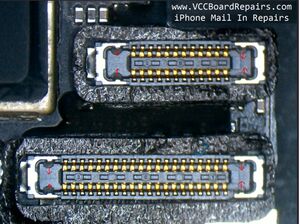
LCD Connector: [ edit | edit source ]
Diode mode the LCD connector (J4502) and check for any shorts (0.000 V) or OL on a line where there should be a reading (≈200–700 mV).
Generally, a line labeled with «LCM» is related to image. Think of «LCM» as «LCd iMage».
Often times, you’ll find one these lines shorted to ground:
PP5V7_LCM_AVDDH_CONN
PP5V7_MESON_AVDDH_CONN
PN5V7_LCM_MESON_AVDDN_CONN
If shorted, you’ll need to inject voltage to find the shorted capacitor.
Please note: Inject no more than 5.7 V but it is recommended to inject like 2 V or 3 V and see if that’s enough to find the short. Injecting 5.7 V will inject too much power too quickly and cause the heat to spread really fast and hard to pinpoint the shorted capacitor.
Sometimes, you’ll find an OL reading at PP1V8_LCM_CONN. If so, find FL3906 and check for pry damage or blown filter. Replace if you get a diode mode reading on one side of the filter, but OL on the other. Both sides of the filter should give you the same diode mode reading.
If diode mode reading at the LCD connector is good, check Chesnut (U3703), which is responsible for image.
Check C3703 for continuity across it. It should not have any. If there is continuity, replace it.
Check if there’s any water damage under Chesnut. Lift the IC and see if any corrosion is present. If so, clean corrosion and replace Chesnut and test again.
If still no image, diode mode the pads underneath Chestnut and check for any shorts or OL on a line where there should be a reading.
If you find a shorted line, track down the shorted capacitor by injecting voltage
If you find an OL where there should be a reading, follow the path of the line and diode mode every at every point. Find the point where the diode mode reading reappears. That should be where the line is disconnected and you’ll need to replace the component that disconnected the line, usually a filter.
If no abnormal readings under Chestnut, just replace Chestnut and test again.
No Touch — Phone turns on but touch doesn’t work
Symptoms:
With a known good screen, phone turns on but no touch
Troubleshooting Steps and Solutions
Diode mode the LCD connector (J4502) and check for any lines that are OL or 0.000 V (shorted).
In most cases, you’ll find pry damage near the connector, causing damage to a filter or resistor. Commonly damaged:
FL3917
FL3910
R3923
If you find an abnormal diode mode value, see if the name of the line mentions the word «touch. This will help assure you that you’re looking at the right spot
Follow the path of the abnormal value by doing diode mode readings on every component in the path, to see where the correct diode mode reading is located. That will point you towards the failed component.
For example, if the top side of FL3917 gives you OL, but the bottom side of it gives you 0.442, then you found your failed component.
If you found the diode mode readings are all normal, then most likely it’s a connector issue
Find the 4 ground pins on the LCD and Home Button connectors and use fine tip tweezers or an Xacto blade to bend them outwards.
Refer to the example image below
Usually this issue is caused from too many screens being unplugged and plugged in, causing those pins to be pushed outwards
Or from someone plugging in a 8/8P screen into a 7/7P board.
If still no touch, you can try replacing the LCD connector to see if that solves it.
Bootlooping — Error 9
You’ll want to check these first to confirm you have a board issue:
Get a known good screen, charging port and battery — Helps validate that you have a board issue.
Get a known good OEM iPhone cable
Flash with 3uTools using Easy Flash
Flash with 3uTools using iTunes Flash
Solution: [ edit | edit source ]
If 3uTools Easy Flash gives you a failure at 19% or 20% and 3u Tools iTunes Flash gives you Error 9, then the issue is NAND. You’ll need to replace NAND. NAND is the memory/storage chip.
Compatible NANDs [ edit | edit source ]
For iPhone 7 and 7 Plus, you can use the NAND of any of the following devices interchangeably:
iPhone 6S
iPhone 6S Plus
iPhone SE (1st Gen)
iPad Pro 9.7
iPad Pro 10.5
iPad Pro 12.9 Gen 1
iPad Pro 12.9 Gen 2
iPad 5th Gen
iPad 6th Gen
iPad 7th Gen
NAND Programming Process [ edit | edit source ]
In order to successfully replace the NAND, you’ll need the following from the original device or NAND and write it to the replacement NAND, otherwise it won’t activate.
SN (Serial Number)
WiFi Mac Address
BT (Bluetooth) Mac Address
It’s also recommended you set these to the correct values, but technically will function fine if you put different values
Region (USA, China, Japan, UK, etc.)
LL/A is for USA
Color (Black, White, Rose Gold, Red, etc.)
This sets the boot up color of the screen. iPhones with a white screen will boot with a white background and black Apple Logo and vice versa for black screen devices.
Tools [ edit | edit source ]
You can use any NAND programmer that supports iPhone 7/7P.
JC P7 seems to be the most popular.
iRepair P10 is another option, that does NAND programming via the lightning port and uses the available «Purple Mode» exploit.
What if I don’t have the original NAND data? [ edit | edit source ]
You can get the required NAND info from above, by reading the original NAND from the device.
In most cases, you should be able to read the NAND data.
If it can’t, you’ll need to find it elsewhere
GSX report (You’ll need to find someone who offers this service)
MagicCFG Recovery (requires Jailbreak)
Sometimes, the GSX report service is not available.
Using MagicCFG Recovery
First, you’ll need to install the replacement NAND, with any generic data filled in for SN, WiFi, BT, etc..
Then restore the phone
Then you need to jailbreak the device with Checkra1n
After, run the MagicCFG Recovery tool, which will capture the SN, WiFi/BT Mac addresses.
Then go back, read the NAND, edit the SN, WiFi, BT addresses and write them again into the NAND
Then restore one more time
Now you should be able to activate the device.
Random Restarting (Usually after 3 minutes)
You’ll want to check these first to confirm you have a board issue:
Get a known good screen, charging port and battery — Helps validate if you have a board issue.
Get a known good OEM iPhone charging cable and brick.
Symptoms [ edit | edit source ]
Phone will fully boot up and get to the home screen but after about 3 minutes, it will just spontaneously restart
You’ll notice the battery level is sporadic (value constantly changes) or stays at 0% or 1%, even if battery is fully charged
You see it’s not charging, where USB meter charging current is jumping all over the place, instead of a 1+ A current draw via USB.
In Settings > Battery > Battery Health, it says «Service» and no battery health percentage.
In 3u Tools, it shows no battery data.
If you see any or all of the symptoms above, it is usually a sign the phone cannot «talk» to the battery.
TIGRIS_BATTERY_SWI_CONN is responsible for transmitting data from the battery to Tigris to the CPU.
Solution [ edit | edit source ]
In most cases, the battery connector is warped or damaged
You can visually inspect the small center pins of the battery connector. If they look like they’re «pushed out» and hidden under the plastic of the connector, you can try pushing them back out with a tool
Or you can replace the battery connector itself.
Sometimes, Tigris has an issue and needs to be replaced.
If this also doesn’t solve it, it could be Tristar or another line under Tigris or Tristar having an issue.
You’ll need to diode mode each pad under Tigris and Tristar to see if you can find an OL or a short, causing the issue.
If you find a shorted line, track down the shorted capacitor by injecting voltage
If you find an OL where there should be a reading, follow the path of the line and diode mode every at every point. Find the point where the diode mode reading reappears. That should be where the line is disconnected and you’ll need to replace the component that disconnected the line, usually a filter.
Final Testing [ edit | edit source ]
Run the stopwatch and see if it can run for longer than the 3 minutes that it was rebooting at
Play a 1hr Youtube video to see if it can play it continuously
Check the USB charging current
Check the Battery Health in the Settings
Check if the battery level is showing accurate battery levels.
Phone will restart when you make a phone call
Symptoms: [ edit | edit source ]
When you make a call, the phone will instantly restart or shut off.
Testing and Solution: [ edit | edit source ]
Unplug the Front Facing Camera, then test again
If the issue is solved, then plug in a new front-facing camera flex cable and try again
Explanation: [ edit | edit source ]
Usually this is caused by the ALS or proximity sensors getting some corrosion from liquid damage.
It’s easier to just replace the part, but sometimes, you can clean off the corrosion with a toothbrush and isopropyl alcohol and get the flex working again.
Symptoms: [ edit | edit source ]
You get no image from the screen
You plug into computer and iTunes/3U tools detects it in DFU mode
If you try to Update or Restore, you get these results:
iTunes Error Code: Error 4014
3u Tools Easy Flash: Fails at 19%
Cause: [ edit | edit source ]
Error 4014 is usually «NAND not detected».
Solutions: [ edit | edit source ]
Check the caps around NAND to see if they’re shorted.
If there’s a short, remove the shorted cap and try to boot the phone up.
If no short, pull the NAND and connect it to the JC P7 NAND programmer and see if it’s readable
If it doesn’t read, the NAND is dead and needs to be replaced
If it does read a NAND, then you can reball NAND and install it again. The phone should boot right up.
Home Button will rapid click when you press it
Please Note: iPhone 7 and 7 Plus Home Buttons are paired to the phone, so you cannot replace the home button. If you do, the home button will completely stop functioning. No click and no Touch ID.
Only Apple, AASP, and IRP are able to replace home button and get home button function and Touch ID function working.


 Andriiko