- Input and Output Devices
- Input Devices
- Keyboard
- Mouse
- Joystick
- Light Pen
- Scanner
- OCR
- Bar Code Reader
- Web Camera
- Output Devices
- Monitor
- Printer
- Sample Questions
- Android Things: Peripheral Input/Output
- Working With Different Interfaces
- I 2 C
- Advanced I/O and Future Updates
- Native I/O
- WiFi and Bluetooth
- Cameras and Displays
- Conclusion
Input and Output Devices
An input/output device, often known as an IO device, is any hardware that allows a human operator or other systems to interface with a computer. Input/output devices, as the name implies, are capable of delivering data (output) to and receiving data from a computer (input).
An input/output (I/O) device is a piece of hardware that can take, output, or process data. It receives data as input and provides it to a computer, as well as sends computer data to storage media as a storage output.
There are many IO Devices available, some of them are:
Attention reader! All those who say programming isn’t for kids, just haven’t met the right mentors yet. Join the Demo Class for First Step to Coding Course, specifically designed for students of class 8 to 12.
The students will get to learn more about the world of programming in these free classes which will definitely help them in making a wise career choice in the future.
Input Devices
Keyboard
The keyboard is the most frequent and widely used input device for entering data into a computer. Although there are some additional keys for performing other operations, the keyboard layout is similar to that of a typical typewriter.
Generally, keyboards come in two sizes: 84 keys or 101/102 keys, but currently keyboards with 104 keys or 108 keys are also available for Windows and the Internet.
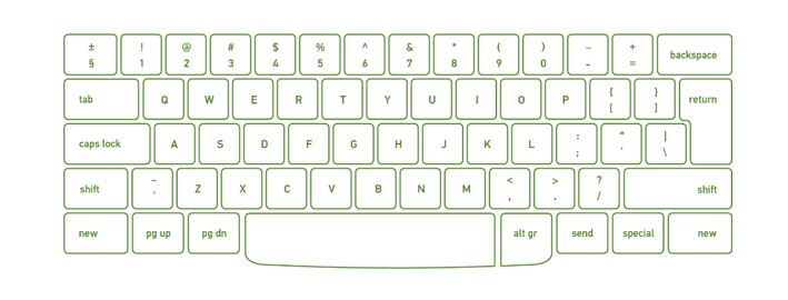
Types of Keys
- Numeric Keys: It is used to enter numeric data or move the cursor. It usually consists of a set of 17 keys.
- Typing Keys: The letter keys (A-Z) and number keys (09) are among these keys.
- Control Keys: These keys control the pointer and the screen. There are four directional arrow keys on it. Home, End, Insert, Alternate(Alt), Delete, Control(Ctrl), etc., and Escape are all control keys (Esc).
- Special Keys: Enter, Shift, Caps Lock, NumLk, Tab, etc., and Print Screen are among the special function keys on the keyboard.
- Function Keys: The 12 keys from F1 to F12 on the topmost row of the keyboard.
Mouse
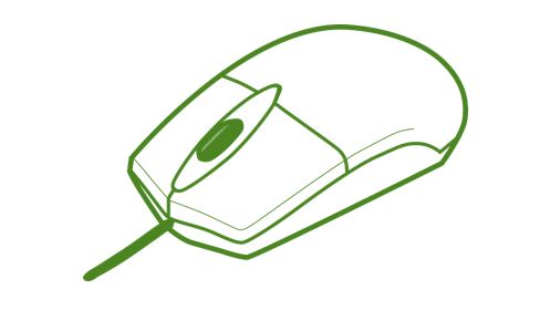
The most common pointing device is the mouse. The mouse is used to move a little cursor across the screen while clicking and dragging. The cursor will stop if you let go of the mouse. The computer is dependent on you to move the mouse; it won’t move by itself. As a result, it’s an input device.
A mouse is an input device that lets you move the mouse on a flat surface to control the coordinates and movement of the on-screen cursor/pointer.
The left mouse button can be used to select or move items, while the right mouse button when clicked displays extra menus.
Joystick
A joystick is a pointing device that is used to move the cursor on a computer screen. A spherical ball is attached to both the bottom and top ends of the stick. In a socket, the lower spherical ball slides. You can move the joystick in all four directions.
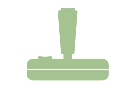
The joystick’s function is comparable to that of a mouse. It is primarily used in CAD (Computer-Aided Design) and playing video games on the computer.
Light Pen
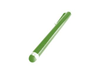
A light pen is a type of pointing device that looks like a pen. It can be used to select a menu item or to draw on the monitor screen. A photocell and an optical system are enclosed in a tiny tube.
When the tip of a light pen is moved across a monitor screen while the pen button is pushed, the photocell sensor element identifies the screen location and provides a signal to the CPU.
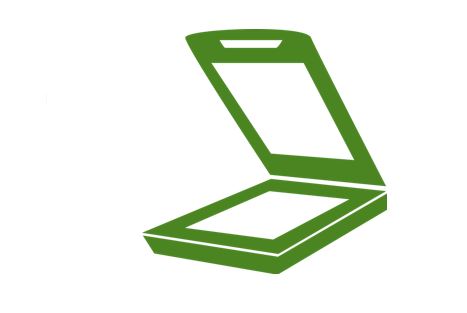
Scanner
A scanner is an input device that functions similarly to a photocopier. It’s employed when there’s information on paper that needs to be transferred to the computer’s hard disc for subsequent manipulation.
Scanner collects images from the source and converts them to a digital format that may be saved on a disc. Before they are printed, these images can be modified.
OCR
OCR stands for optical character recognition, and it is a device that reads printed text. OCR optically scans the text, character by character, turns it into a machine-readable code, and saves it to the system memory.
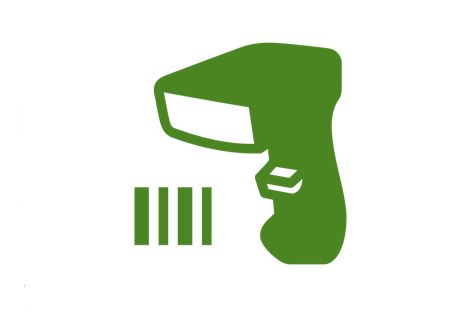
Bar Code Reader
A bar code reader is a device that reads data that is bar-coded (data that is represented by light and dark lines).
Bar-coded data is commonly used to mark things, number books, and so on. It could be a handheld scanner or part of a stationary scanner.
A bar code reader scans a bar code image, converts it to an alphanumeric value, and then sends it to the computer to which it is connected.
Web Camera
Because it records a video image of the scene in front of it, a webcam is an input device. It is either built inside the computer (for example, a laptop) or attached through a USB connection.
A webcam is a computer-connected tiny digital video camera. It’s also known as a web camera because it can take images and record video. These cameras come with software that must be installed on the computer in order to broadcast video in real-time over the Internet. It can shoot images and HD videos, however, the video quality isn’t as good as other cameras (In Mobiles or other devices or normal cameras).

Output Devices
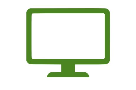
Monitor
Monitors, also known as Visual Display Units (VDUs), are a computer’s primary output device. It creates images by arranging small dots, known as pixels, in a rectangular pattern. The amount of pixels determines the image’s sharpness.
The two kinds of viewing screen used for monitors are:
(1) Cathode-Ray Tube (CRT): Pixels are minuscule visual elements that make up a CRT display. The higher the image quality or resolution, the smaller the pixels.
(2) Flat-Panel Display Cathode-Ray Tube Monitor: In comparison to the CRT, a flat-panel display is a type of video display with less volume, weight, and power consumption. They can be hung on the wall or worn on the wrist.
Flat-panel displays are currently used in calculators, video games, monitors, laptop computers, and graphical displays.
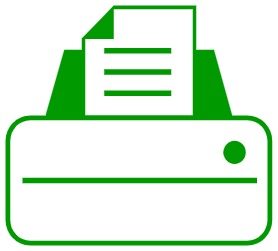
Printer
Printers are output devices that allow you to print information on paper.
There are two types of printers:
(a) Impact Printer:
Characters are printed on the ribbon, which is subsequently crushed against the paper, in impact printers. The following are the characteristics of impact printers:
- Exceptionally low consumable cost.
- Quite noisy
- Because of its low cost, it is ideal for large-scale printing.
- To create an image, there is physical contact with the paper.
(b) Non-Impact Printers:
Characters are printed without the need for a ribbon in non-impact printers. Because these printers print a full page at a time, they’re also known as Page Printers. The following are the characteristics of non-impact printers:
- Faster
- They don’t make a lot of noise.
- Excellent quality
- Supports a variety of typefaces and character sizes
Sample Questions
Question 1. List Disadvantages of CRT Monitor.
Answer:
Some of the disadvantages of CRT are :
- High power consumption
- Big back and take up a lot of desk space.
- Because it is less bright than an LCD, it is not ideal for excessively bright environments.
- They’re big, heavy, and clumsy.
Question 2. Compare input & Output Devices.
Answer.
| S.No | Input Device | Output Device |
| 1. | Data is accepted from the user of the device | It shows the data after processing to the user |
| 2. | It accepts the user’s data and transmits it to the processor for saving in the secondary memory or processing. | It receives the data from the processor and returns it to the user. |
| 3. | More complex designing | Less complex designing |
| 4. | These devices are used to accept the data | These devices are used to display or show the data |
| 5. | Example: Keyboard, mouse, etc. | Example: Monitor, Printer, etc. |
Question 3. What are the types of flat-panel displays?
Answer:
There are 2 types of flat-panel displays :
(a) Emissive Display: Devices that turn electrical energy into light are known as emissive displays. Example: LEDs, Plasma panels, thin film electroluminescent displays etc.
(b) Non- Emissive Display: Optical effects are used in Non-Emissive displays to turn sunshine or light from another source into graphical patterns. LCDs are a good example (Liquid Crystal Device).
Question 4. Explain the output device: Plotter.
Answer:
A plotter is a device that prints graphics in a variety of color formats with high-quality images. It’s similar to a printer, but with more advanced capabilities.
Plotter allows us to create pictures, 3D postcards, advertising signs, charts, and various designs of the internal structure of building machines, as well as print large maps, architectural drawings, large-format printing, and create pictures, 3D postcards, advertising signs, charts, and various designs of the internal structure of building machines.
Question 5. Compare Impact & Non-Impact Printers.
Источник
Android Things: Peripheral Input/Output
Android Things has a unique ability to easily connect to external electronics components with the Peripheral API and built-in device support. In this article you will learn about the different types of peripherals you can connect to in order to customize your IoT devices with Android Things.
Working With Different Interfaces
Android Things allows most devices to be connected to your prototyping board through the use of the Peripheral API, which supports GPIO, PWM, I 2 C, SPI and UART interfaces, each of which are industry standard interfaces for communicating with peripherals. In this section you will learn what these interfaces are, and how to communicate with devices that you have hooked up to your Android Things prototyping board using these connections.
General Purpose Input/Output (GPIO) pins are used for digital (binary) communication with components, such as reading whether a button is pressed or not, or turning an LED on or off. Of the I/O methods that you will see in this tutorial, GPIO is by the simplest to use, only requiring one pin and using boolean values for high or low states.
Before you can connect to a GPIO pin, you will need to know the unique name of that pin. You can get the names of all available pins by retrieving the PeripheralManagerService and calling getGpioList() . On a Raspberry Pi, this will return the following list:
To figure out which pins each of these represent, you can refer to the Raspberry Pi I/O diagram.


Once you have the name of the pin that you will be reading from or writing to, you can get a Gpio object reference to that pin by calling openGpio(String pin_name) from your PeripheralManagerService .
GPIO pins can be used for input or output. If you will use the pin to read in information, you will need to configure the pin direction as DIRECTION_IN , and set the trigger type for that pin so that it knows when to let your apps know that something has occurred.
The trigger types consist of EDGE_NONE , EDGE_RISING , EDGE_FALLING , and EDGE_BOTH . If a button is pressed, then a rising event occurs as the button circuit is completed and a high-voltage signal appears on the physical pin. A falling event happens when the button is released. Your code will be notified of changes based on the type of trigger you set.


Now that your GPIO is listening for edge triggers, you will need to create a GpioCallback to register the value of the GPIO component within your app.
Once your callback is created, register it with your Gpio object.
If your GPIO pin is writing information, then you will need to set the direction as DIRECTION_OUT_INITIALLY_LOW or DIRECTION_OUT_INITIALLY_HIGH , depending on whether you want the component to start as on or off. No trigger types are required for an output pin.
In order to write to the device, you can call setValue(boolean) on the Gpio object to set the state of the component.
Once your app is done running, you will need to unregister your input callback, if it was created and registered, and close access to the peripheral using the close() method in onDestroy() .
Pulse Width Modulation (PWM) devices use the alternation of digital states, known as a proportional control signal, to function. There are three major parts of a proportional control signal to be aware of:
- Frequency: This describes how often the output pulse repeats. The unit of measurement for frequency is hertz (Hz).
- Duty Cycle: This represents the width of a pulse within a set frequency. Duty cycle is expressed as a percentage of high signals within a frequency, so a cycle that is up half of the time would have a 50% duty cycle.
- Period: This represents the time it takes for each up/down cycle to occur. Period is inversely related to frequency.
By adjusting the duty cycle of a signal, you can control the average ‘on’ time of a wave. Below you can see an example of a 50% period signal.


Some devices that can use a PWM signal include servo motors, which use the frequency to determine their position, or an LED matrix, that can use the PWM signal to adjust brightness.


Even with just motors and GPIO devices, you can create a large number of IoT devices, such as a «smart» cat tree with motorized laser.

Similarly to GPIO, you can retrieve a list of available PWM ports by creating a PeripheralManagerService and calling getPwmList() . On a Raspberry Pi, this list will look like the following:
Once you know the name of the PWM pin that you want to use, you can open a connection to that peripheral using the openPwm(String) method. This will need to be wrapped in a try/catch block to handle the possibility of a thrown IOException .
Once you have opened a connection to your PWM pin, you can control settings on it, such as the frequency and duty cycle.
Before you finish with your app and destroy the Activity , you will need to close the connection and release the reference to your PWM device.
I 2 C
The Inter-Integrated Circuit (I 2 C) bus allows your project to communicate with multiple devices over one physical connection, and it allows you to send complex data with only a few pins of your Pi or other embedded device. I 2 C uses synchronous communication between devices, and relies on a clock signal to ensure that devices are responding at the appropriate time.
The device that issues the clock signal, which will often be your Android Things device, is known as the master, and all connected peripherals that receive that signal are known as slaves.
Unlike PWM and GPIO, which only require a single pin, I 2 C devices require three connections:
- Shared clock signal (abbreviated SCL), which issues the clock signal from the master device to the slave devices.
- Shared Data Line (abbreviated SDA), which is the connection used for actual data transfer. Because I 2 C is a synchronous (half-duplex) communication standard, meaning data can only move in one direction at a time, only one device may use this connection at any particular point in time.
- An electrical ground connection.
It’s worth noting that every I 2 C slave device is programmed with a set address, and will only respond when the master device makes a data request for that particular address.


Some peripherals that can use this connection method include segmented LED matrix displays, and various advanced sensors.


Each Android Things device will have a set of pins that are used for I 2 C, which you can find by looking at the documentation for your specific prototyping board. For the Raspberry Pi, you can reference the pinout image at the top of this article, which states that the SDA and SDL are pins 3 and 5. To find the name of your I 2 C, you can run the following code:
The above code snippet will output the following on a Raspberry Pi:
Once you know the name of your I 2 C bus, you can connect to devices on that bus using their software address. You can find software address and other low-level connection details in the peripheral component’s «datasheet»—required reading if you want to use a peripheral for an embedded project!
When communicating with a device over I 2 C, you can use the System Management Bus (SMBus) protocol to place data inside of registers or to retrieve data that has been saved in registers on each peripheral device. This is done using the device address and register address, and Android Things allows you to read or write individual bytes from a register or groups of bytes from multiple registers with the following methods:
- readRegByte() and writeRegByte() : Read or write a single byte from a specific register.
- readRegWord() and writeRegWord() : Read or write bytes from two sequential registers on a peripheral in little-endian format.
- readRegBuffer() and writeRegBuffer() : Read or write bytes from up to 32 consecutive registers. Values are written or retrieved as a byte array .
When your app is ready to close on your Android Things device, be sure to unregister your I 2 C bus.
Serial Peripheral interface (SPI) connections work similarly to I 2 C connections, except they support full-duplex communication. This means that data can be read and written to peripherals simultaneously, rather than requiring the master device to request information from the slave peripherals. A clock signal is still required to control data flow from multiple devices on the SPI signal bus. SPI requires a minimum of four connections to function:
- Master Out Slave In (MOSI)
- Master In Slave Out (MISO)
- Clock signal (CLK)
- Shared ground (GND)
In addition, a fifth connection is required if multiple SPI devices are attached to an SPI bus. This is the Chip Select (CS), which is used to signal the hardware address of peripherals, so that your master device can communicate with a specific slave.
Some examples of peripherals that use SPI include LED dot matrix boards and SD card readers, and it’s worth noting that many peripherals that support I 2 C will also support SPI.


Just like the previous examples, you will need to know the name of the SPI connection on your Android Things board. You can find this by creating a PeripheralManagerService and calling getSpiBusList() on that object. On a Raspberry Pi you will have the following available:
Once you know the name of the SPI bus that you will use, you can open a connection to it.
In order for devices to communicate over the SPI bus, they all must «speak the same language», which is to say they must be configured for the same clock rate and data format. While some peripherals can adjust their data format and clock rate, others cannot. As all devices on an SPI bus must operate with the same configuration, it is important to know the capabilities of your peripherals before attempting to include them on your SPI bus. There are four settings/parameters that will need to be set for your SPI bus:
- SPI mode: The SPI mode has two major components: whether the clock signal is high or low while no data is being transferred, and which edge of a pulse is used for transferring data.
- Frequency: This represents the shared clock signal in Hz, and will most likely be a value determined by the capabilities of your slave devices.
- Bit justification: Used to set the endianness for your data. By default, Android Things will use big-endian, putting the most significant big (MSB) first.
- Bits per word (BPW): Controls how many bits will be sent to a slave device before toggling the chip select signal. By default, eight bits per word will be sent.
In your Android Things java code, you can set these four values on your SPI bus like so:
How you interact with your devices on the SPI bus depends on whether you are operating in full or half-duplex mode. If your devices are configured for half-duplex, then you will want to exchange data between the slaves and master device with the read() and write() methods on the SpiDevice object. If you are operating in full-duplex mode, then you will want to use the transfer() method with two byte array buffers: one with the data to be sent, and another empty buffer for storing response data.
When your app is ready to close on your Android Things device, be sure to unregister your SPI device.
More complex peripherals, such as LCD displays, SD card readers, and GPS modules, will often use serial communication through UART ports when communicating with a master device. UART allows devices to asynchronously send raw data to a buffer on another device. This buffer is then read in a first-in-first-out order. It also allows both data format and transfer speed to be configured on both connected devices. Both devices must agree on a transfer speed, as UART does not support a clock signal, but transfer speeds tend to be faster than I 2 C and data can be transferred in full-duplex mode between devices. Unlike I 2 C and SPI, only one attached peripheral is allowed per UART connection.
UART peripherals have three core wires:
- RX, which is used to receive data.
- TX, which is used to transmit data.
- GND, electrical ground.


On peripheral components, these pins will generally be labeled like so:


In addition, some UART devices may include two more connections for controlling data flow:
- Request to Send (RTS)
- Clear to Send (CLS)


Similar to all of the previous examples, you will need to know the name of your Android Things device’s UART connection. You can find that with the following code:
On a Raspberry Pi, the log output will look like this:
Once you know the name of your UART connection, you can create an Android Things UART device in the same way you have opened other device connections.
Once you have your device, you will need to configure the format for the data frames that will be sent between devices. There are four properties to be aware of:
- Number of data bits: UART can send between five and nine bits to represent a character of data. Sending less bits allows for a faster data transfer rate, but limits the range of characters that can be sent.
- Parity bit: Used to check if the content of a transmission’s data sums to an even or odd number. If parity is set to none, then the parity bit is removed from the transmission. This is used for error checking on transmissions.
- Stop bits: This can be set to either 1 or 2 bits. The transmission will idle for a duration equal to the number of stop bits to indicate that a data frame has ended.
- Baud rate: Baud rate is the transmission speed for your data frame. Since there are no clock signals in UART, both devices must be configured with a baud rate before transmission begins.
Each of these settings can be configured on a UART device like so:
Earlier you learned that there are two wiring settings for UART devices, those with additional control signals, and those without. You can configure your UART device in code by using the setHardwareFlowControl() method.
Once you’ve finished configuring your devices, it’s time to read and write data from your Android Things board and your UART peripheral. Writing is handled by calling the write() method with a byte array buffer and the length of that array.
While you can continuously poll for data in your device’s read buffer, your better bet is to create a UartDeviceCallback object, which provides a method named onUartDeviceDataAvailable() that will be triggered when data is available. When it is, you can read data from your device’s data buffer. You will be able to associate this callback with your UART device with the registerUartDeviceCallback , though you will need to remember to call unregisterUartDeviceCallback when you are done using the callback. When data is available, you can retrieve it by using the UART read() method.
When you are finished with your Activity , be sure to close and nullify the reference to your UART device.
Advanced I/O and Future Updates
While the Peripheral API allows you to communicate with almost any device that can be wired to your Android Things board, Google has provided some additional support to make building your IoT devices even easier. This section will take a look at some of the additional peripheral support available through Android Things.
Native I/O
While Android Things provides a simple way for Android developers to get into IoT development with the Android SDK and Java, many IoT apps already exist in C and C++, and other developers would prefer to work in those languages for various reasons. To support this, Google has supplemented the Peripheral API with support for native applications and the NDK. I won’t go into depth on this topic, but the connections are established and used in very similar ways to those discussed above.
WiFi and Bluetooth
Without a way to connect to the Internet, IoT devices would simply be things. With built-in wireless support, your Android Things devices can connect to the Internet and use various online resources, such as Firebase and other Google services, or any other back-end service. In addition, using tools such as Google Play Services and the Nearby Connections API can allow users to communicate directly with your device over their WLAN network.
Although not currently enabled in the developer preview versions of Android Things, Bluetooth connectivity is also an important IoT capability. Using Bluetooth, you can create multiple IoT devices or accessories and have them communicate across short distances. This allows each device to have additional contextual information about its environment, such as a user’s home or workspace, in order to best serve the user.
Some devices do work with prototype board USB ports, although it’s not entirely enabled in the current iteration of the Android Things developer preview. In the second developer preview, Google has added USB audio out with text to speech support, and developers have confirmed that other devices work, such as USB microphones. As USB APIs are tested and approved in later versions of Android Things, there will be a wide array of devices that can be simply plugged into your IoT device as an accessory.
Cameras and Displays
Some devices, such as the Raspberry Pi, come with additional I/O connections built in, such as HDMI, Display, and Camera. Luckily, all of these are enabled with Android Things, allowing you to attach a camera with a 15cm ribbon cable.


. or a display through a ribbon cable or HDMI connection:
.jpg)
.jpg)
.jpg)
Conclusion
Congratulations! You’ve covered a lot of ground, but have learned incredibly valuable information about connecting and controlling peripheral devices with an Android Things board. Using this knowledge, you should be able to connect and communicate with various hardware components.
In the next post of this series, we will use our knowledge of the Peripherals API to create a software driver for a GPIO motion sensor component, which can then be used in a larger Android Things project.
In the meantime, check out some of our other tutorials and articles about Android development!
Источник