- Айфон 7 не включается
- Айфон 7 не включается
- Инструменты и оборудование
- iPhone 7
- Symptoms: [ edit | edit source ]
- Solution: [ edit | edit source ]
- Symptoms: [ edit | edit source ]
- Solution: [ edit | edit source ]
- Another Possible Cause: [ edit | edit source ]
- Diagnosing [ edit | edit source ]
- Step 1: Rule Out Parts Issues [ edit | edit source ]
- Additional Tests [ edit | edit source ]
- Step 2: Tristar Testers (optional) [ edit | edit source ]
- Step 3: DC Power Supply Boot Up Consumption [ edit | edit source ]
- Step 4: Check Tristar for Heat (Optional) [ edit | edit source ]
- Step 5: Check Voltage at the Battery Connector [ edit | edit source ]
- Solution: [ edit | edit source ]
- Replace Tristar [ edit | edit source ]
- After Replacing Tristar [ edit | edit source ]
- Other Possible Charging Faults [ edit | edit source ]
- Diagnosing [ edit | edit source ]
- 1. Make a call [ edit | edit source ]
- 2. Voice Memo App [ edit | edit source ]
- Solution [ edit | edit source ]
- Reball Audio IC U3101 and add C12 and D12 Jumpers [ edit | edit source ]
- Making The Jumpers Under Audio IC U3101 [ edit | edit source ]
- C12 [ edit | edit source ]
- D12 [ edit | edit source ]
- Other Jumpers [ edit | edit source ]
- The Audio IC Chip — Reuse or Replace? [ edit | edit source ]
- Underfilled Audio IC [ edit | edit source ]
- Final Testing [ edit | edit source ]
- Symptoms: [ edit | edit source ]
- Cause: [ edit | edit source ]
- Solution: [ edit | edit source ]
- Symptoms: [ edit | edit source ]
- Cause: [ edit | edit source ]
- Intel Model [ edit | edit source ]
- Qualcomm Model [ edit | edit source ]
- Solutions: [ edit | edit source ]
- Intel Model [ edit | edit source ]
- Qualcomm Model [ edit | edit source ]
- Symptoms [ edit | edit source ]
- Solution [ edit | edit source ]
- Diagnosing [ edit | edit source ]
- You’ll want to check these first to confirm you have a board issue: [ edit | edit source ]
- Solution [ edit | edit source ]
- Troubleshooting Steps and Solutions [ edit | edit source ]
- LCD Connector: [ edit | edit source ]
- Chestnut (U3703) — Image IC [ edit | edit source ]
- Solution: [ edit | edit source ]
- Compatible NANDs [ edit | edit source ]
- NAND Programming Process [ edit | edit source ]
- Tools [ edit | edit source ]
- What if I don’t have the original NAND data? [ edit | edit source ]
- Symptoms [ edit | edit source ]
- Solution [ edit | edit source ]
- Final Testing [ edit | edit source ]
- Symptoms: [ edit | edit source ]
- Testing and Solution: [ edit | edit source ]
- Explanation: [ edit | edit source ]
- Symptoms: [ edit | edit source ]
- Cause: [ edit | edit source ]
- Solutions: [ edit | edit source ]
Айфон 7 не включается
Айфон 7 не включается – с такой неисправностью прислали телефон на ремонт из другого города. При подключении к USB-tester iPhone 7 не включается и не заряжается. При этом нагревается задняя часть смартфона. Предположительно в плате короткое замыкание. Последующий ремонт проводился во время обучения пайке bga, в сервисном центре.
Айфон 7 не включается
Первое, что необходимо сделать – разобрать iPhone 7. При подключение к ЛБП и после нажатия на кнопку включения айфон 7 не включается и амперметр фиксировал наличие потребления тока в 2 Ампера при рабочем напряжении 3,8 Вольта. И сильно нагревался основной контроллер питания айфон 7 – U1801.

Основной контроллер питания iPhone 7
Предполагаем наличие короткое замыкание.
Используя автоматический мультиметр Fluke проверили основные цепи питания телефона на наличие в них рабочих сопротивлений.
А именно, в каких цепях проводились измерения:
- PP_BATT_VCC
- PP_VDD_MAIN
- PP3V0_NAND
- PP1V8
- PP0V9_NAND
- PP_VDD_BOOST
Сопротивления в вышеперечисленных цепях соответствовали сопротивлениям рабочего устройства.
Принято решение демонтировать основной контроллер питания, для проведения дальнейшей диагностики. Так как в основных цепях КЗ не выявлено, а КП нагревается. По мнению многих мастеров по ремонту телефонов, самый эффективный способ определения короткого замыкания – это использовать тепловизор. Намного ускоряет время поиска КЗ и соответственно сокращается время ремонта.
Так как CPU (U0700) и Baseband (BB_RF) покрыты компаундом и располагаются с обратной стороны платы, напротив КП, есть риски нарушить пайку выводов этих микросхем (перегрев платы). Во избежание перегрева центрального процессора или модема, принято решение спилить основной контроллер питания на фрезерном станке ЧПУ.

Замена контроллера питания iPhone 7
Следующий шаг – подготовка контактной площадки:
- сплавом Розе пропаяли контактную площадку содержащую бессвинцовый припой;
- медной оплеткой собрали остатки припоя;
- убрали остатки компаунда. Именно наличие компаунда под микросхемой повышает риски при выпаивании U1801.

Контактная площадка основного КП iPhone 7
Используя Zillion x Work, а именно карту падения напряжений на контактной площадке основного КП, произвели замеры. Для этого необходимо перевести мультиметр в режим диодной прозвонки.
Все падения напряжений соответствовали рабочим.
Можно сделать следующий вывод: айфон 7 не включается, по причине короткого замыкания в самой микросхеме U1801 (КП).
Для дальнейшего ремонта приобретен новый контроллер. Обязательная процедура – перекатка чипа на свинец содержащий припой.
Следующий шаг – это монтаж микросхемы:
- во избежание перегрева, установили теплоотводы;
- на контактную площадку нанесли небольшое количество флюса Flux Plus;
- с позиционировали, перекатанный чип на контактной площадке по ключу;
- феном Quick 857DW+, припаяли U1801.

Теплоотводы на плате iPhone 7
Выждав время, для того чтобы понизилась температура, проверили на наличие короткого замыкания. Для этого подключили плату к лабораторному блоку питания и подали напряжение, начиная с минимально допустимого. Короткого замыкания не обнаружено.
Установили (подкинули) плату в корпус iPhone 7 и включили телефон от ЛБП. Айфон успешно включился, потребление тока соответствует рабочему потреблению.
Затем собрали “аппарат” и проверили весь функционал. Для дополнительной проверки подключили смартфон к 3uTools. Так как все исправно работало, ремонт “iPhone 7 не включается” – выполнен.

iPhone 7 не включается
Инструменты и оборудование
Используемые инструменты и оборудование:
- комплект инструмента для ремонта электроники (отвертки, присоска, пинцет, лопатка)
- сепаратор,
- USB тестер,
- фрезерный станок с ЧПУ,
- лабораторный блок питания,
- термовоздушная паяльная станция Quick 857DW+,
- индукционный паяльник,
- мультиметр,
- микроскоп
- универсальный держатель материнской платы.
Один из частых ремонтов айфон 7 – это когда телефон не включается. Чаще всего выходит из строя USB контроллер, реже основной КП. Замена U1801 усложняется наличием компаунда под микросхемой. И тем что основной КП расположен непосредственно над центральным процессором (CPU). Правильно выполнять вышеописанный ремонт вы можете научиться в Bgacenter. Одной из причин, когда телефон не включается, может быть неисправный TRISTAR. Если USB контроллер исправен, то при подключении к блоку и кратковременном нажатии на кнопку включения, амперметр регистрирует первые показания до 90 мА. Если в результате ремонта перестает работать вибро, следует обратить внимание на микросхему HOMER.
Источник
iPhone 7
| Model | Type | Modem | Region |
|---|---|---|---|
| A1660 | 7 | Qualcomm | Global |
| A1778 | 7 | Intel | Global |
| A1779 | 7 | Intel | Japan |
| A1780 | 7 | China | |
| A1661 | 7+ | Qualcomm | Global |
| A1784 | 7+ | Intel | Global |
| A1785 | 7+ | Intel | Japan |
| A1786 | 7+ | China |
| Problem | Solution |
|---|---|
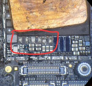
| No Power — Pulls ≈2 A or more before you prompt to boot on DC power supply | Do a full visual inspection of the board and check for water damage under the stickers on the back. Remove the foam around the connectors to get a better look at everything. You’re looking for any signs of corrosion on or around components and ICs. If there is no water damage, is is most likely a shorted capacitor on any of the below lines:
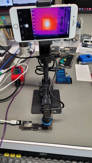
You’ll need to inject voltage (4 V / 2 A) directly into the line you measured as short and use freeze spray (see here https://youtu.be/3MtLSQJvQxI) or thermal camera (see here: https://youtu.be/fkd4iDjgfvc) to spot the capacitor that is shorted. In these cases, you can just remove the shorted capacitor and not replace it. The device will function normally with no negative effects. Replacing it means you are adding more heat to the board to reinstall it, which increases the risk of something going wrong. If you have a case of water damage, then you’ll have to pay attention to the spots on the board where there’s signs of water damage. Often, you’ll find corrosion on capacitors but also under ICs. Common ICs and areas to have corrosion and cause a VDD MAIN short:
You’ll need to visually inspect these areas to see if they’re liquid damaged Please Note: If you are using a DC power supply to inject voltage through the battery connector, like using an iPower Pro or DT880 (see here https://youtu.be/rawjB9yxe1A), be aware that the Tigris Mosfet Q2101 will heat up instantly. This is because the battery connector line PP_BATT_VCC connects to PP_VDD_MAIN through it, which creates lots of heat. Q2101 itself does not have a connection to ground, therefore, it’s impossible for it to be shorted. |
| No Power — Hangs at 0.020–0.030 A after you prompt to boot on DC Power Supply | |
| No Power — After prompt to boot on DC power supply, current jumps back and forth from 0 A to 320 mA, then 0 A to 1.4 A, then 0 A to 500 mA, and so on | |
| Not Charging — Turns on but doesn’t charge. Takes ≈0.006 A via USB power meter. | There are multiple ways to test and diagnose a charging issue/Tristar failure Diagnosing [ edit | edit source ]Step 1: Rule Out Parts Issues [ edit | edit source ]Test the logic board with known good parts, like a known good charging port flex and battery. These are parts that you have previously tested and confirmed they’re good. Sometimes using just new stock is not enough, because sometimes new stock is defective. Ideally, take the board out of the housing and only plug in a screen, battery and charging port to the logic board, then plug it in to charge and check the USB meter. This helps remove all variables, as sometimes, a bad flex can cause charging issues; rare, but it happens. If the current is still around 0.006 A via your USB meter, the phone turns on, but does not show charging symbol, then it’s a board issue. Generally, these scenarios are Tristar — U4001 — Part# 610A3B. But to confirm, we need to do additional tests. Additional Tests [ edit | edit source ]Step 2: Tristar Testers (optional) [ edit | edit source ]You can use a tool called «Tristar Tester», which generally works well with detecting a bad Tristar, although it’s not foolproof. These two are the most popular on the market
Both scan for charging port issue, then Tristar issue.
Use this as one of your clues to a bad Tristar, but don’t trust it to be 100% accurate. In either case, you can continue the diagnosis process to help further confirm a Tristar issue Step 3: DC Power Supply Boot Up Consumption [ edit | edit source ]With a DC power supply or DT880, see what is the power consumption before and after prompt to boot. If you get current draw before prompt to boot, then it’s not Tristar. See above Problem/Solution, as it will be a short on the board. If you don’t get current draw before prompt to boot, but after you prompt to boot, the first number of the current draw of the boot sequence is ≈0.150–0.250 A, then it definitely points towards a bad Tristar (see video at 6:39 https://youtu.be/KAMpmxeaNys?t=399). Step 4: Check Tristar for Heat (Optional) [ edit | edit source ]You can also use a thermal camera or freeze spray to check if Tristar heats up when you prompt to boot. Usually it will get hot when it’s bad, but not always. Step 5: Check Voltage at the Battery Connector [ edit | edit source ]Plug in the charging port flex to the logic board, and nothing else. No screen, no battery, etc. Then plug in the charging cable to the charging port. Set your multimeter to DC volts mode, and measure the positive and negative battery pins of the battery connector J2201. These are the 2 large pins on each side. Polarity for this test doesn’t matter, just ignore the negative symbol if you end up probing in reverse polarity
Solution: [ edit | edit source ]Replace Tristar [ edit | edit source ]After all these tests, you can replace Tristar and see if it’s solved. Tristar for iPhone 7 and 7 Plus requires the version 610A3B. Please make sure to use the correct version, as previous iPhone models use slightly different versions of Tristar. Please Note: Tristar on iPhone 7 and 7 Plus is partially covered by a shield. It is highly recommended that you don’t touch the shield. You should be able to pull off the chip at an angle and place the new Tristar at angle. (See video at 13:22: https://youtu.be/KAMpmxeaNys?t=802) Cutting the shield to get full access to Tristar will risk damaging surrounding components. Also, cutting the shield creates sharp points on the shield, which tend to stick out. This will cause the shield to cut or pierce through the charging port when you put it back into the housing, which will cause No Charging again. After Replacing Tristar [ edit | edit source ]Once you replace Tristar, you can follow the same steps from above to confirm if it’s solved.
You’ll want to compare you previous results to the new results. This tells you if the issue was solved or there’s a problem still present on the board. Please note: Each charging brick is slightly different, so it is recommended to get familiar with your charging brick and cable. Each cable and brick will give slightly different USB charging current readings based on the specs of the current output. You can read the charging brick itself to see the specs. You can get a known good iPhone of the same model and see what the USB charging current is, then compare to the device you are repairing to see if it’s about the same. Also, batteries that are close to a full charge will charge at a lower current than a low battery. Old/worn out batteries also charge at lower rates, as they’re degraded and can’t take as much current. Other Possible Charging Faults [ edit | edit source ]If it still doesn’t charge after replacing Tristar, make sure you followed all the troubleshooting issues above. Then, you’ll want to check for shorts around Tristar. You can probe both sides of each capacitor that’s directly surrounding Tristar and check for continuity to ground. It’s possible that TRISTAR_BYPASS capacitor C4005 is shorted to ground. It is recommended to replace. C4005 value: 1.0 μF, 6.3 V, 0201 package You can also remove Tristar and diode mode all the Tristar pads. Compare the readings on your boardview software, like ZXW to your board. You can also compare diode mode readings to a known good board. If you find any shorts, you’ll need to inject voltage to find the shorted capacitor. |
Audio IC Issue — Grayed out speaker button during a call
Some people also call this «Audio Disease» On older iOS versions, the device will get stuck on Apple logo for ≈7 minutes but then boot up fine and work, but experience audio issues. Diagnosing [ edit | edit source ]These are the two of the best steps to diagnose the Audio IC failure. 1. Make a call [ edit | edit source ]
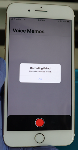
Please Note: Bluetooth audio, including AirPods, will still work fine when an iPhone 7 or 7 Plus has Audio IC issue present. 2. Voice Memo App [ edit | edit source ]
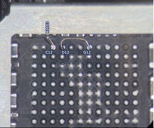
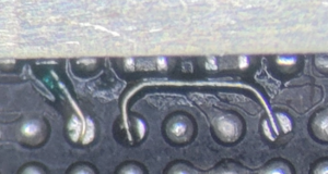
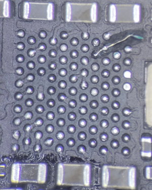
Solution [ edit | edit source ]Warning: Attempting this repair without enough experience with microsoldering, may lead the a «Baseband» issue, where you have «No Service» or non-stop «Searching. » issue. Proceed with caution. Reball Audio IC U3101 and add C12 and D12 Jumpers [ edit | edit source ]The reason why the Audio IC issue occurs is due to the C12 and sometimes the D12 pads under the IC will break. Both of these pads are critical for the audio function of the phone to work. If either of these pads are broken or loose, you’ll get the symptoms mentioned above. Making these 2 jumpers are critical to permanently solving the Audio IC issue, regardless if the pads break during IC removal or prepping the pads with your iron. Do not skip this step. Sometimes, you’ll run into a case where H12 and/or J12 will also break when removing the IC or prepping the pads, but these two pads do not cause the symptoms described above. If either of these two break, it would cause no audio through the lightning port, like using headphones through a lightning to 3.5 mm headphone jack adapter. Adding jumpers for H12 and J12 is optional. Making The Jumpers Under Audio IC U3101 [ edit | edit source ]
C12 [ edit | edit source ]
D12 [ edit | edit source ]
The final result should look something like this:
Other Jumpers [ edit | edit source ]
The Audio IC Chip — Reuse or Replace? [ edit | edit source ]Please note: The root cause of the Audio IC issue is not caused by a bad Audio IC chip, so replacing it is not required. You can reuse the same IC by reballing the IC and placing it back once the jumpers are installed. Sometimes, the IC gets damaged during removal and you will experience these issues:
In this case, replace the IC and that should solve the no ear speaker sound after Audio IC repair attempt. If you experience No Power or Overheating, then try removing the IC and test again. Be aware that the phone will boot without the Audio IC installed. So if the phone boots up without the Audio IC installed and doesn’t overheat, then this confirms the Audio IC chip itself went bad somewhere in the process. Replace the Audio IC in this case. Underfilled Audio IC [ edit | edit source ]If you come across an Audio IC that is underfilled, it is recommended you just replace the IC, as it will be difficult to reball the original and most likely damaged during removal. An underfilled IC is one that has black «glue» holding down the IC. It is believe that Apple started doing this on certain batches to help cover up the widespread Audio IC Issue. You see the whole process of removing the Underfilled Audio IC here: https://www.youtube.com/watch?v=jr5lvCFTgoo Final Testing [ edit | edit source ]
If all tests look good, then the issue is solved. | |
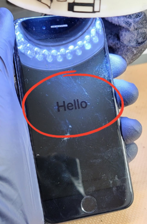
| Stuck in «Searching» or «No Service» after Audio IC Repair attempt Baseband Issue after Audio IC Symptoms: [ edit | edit source ]
Cause: [ edit | edit source ]When too much heat is used when attempting to removed Audio IC or placing it back, the Baseband CPU (BBCPU) on the opposite end, which is underfilled, will disconnect (or float) and cause these problems (In addition) if you’re so sure of your skill on audio IC and you get no service after audio IC, before moving to baseband CPU, first reflow or reball baseband PMU, this is common too. Solution: [ edit | edit source ]This will require you to reball baseband CPU (BBCPU). This process is a bit risky due to CPU being right next to BBCPU and the potential of floating the main CPU is very high. It is recommended to not risk attempting this repair if you don’t have enough experience working with underfilled chips and working next to CPU. Here’s a video of the whole process: https://youtu.be/JP3ghPMjuR0 Please note: If you attempt the above repair, but it’s still stuck in «Searching. » or «No Service», then flash an update (DO NOT RESTORE). This can sometimes solve the issue. Not sure why it is needed sometimes. If a phone with a baseband problem is restored, then the iOS software will «erase» the IMEI (baseband info) in the phone and will require the board issue to be fixed, then restored again, so the software will bring back the IMEI. If you restore, and still has no IMEI, then a baseband/board issue is still present on the board. That will need to be fixed, then restored again. | |
Developed the issue with the phone stuck in «Searching» or «No Service» on its own (no previous repair attempts) Symptoms: [ edit | edit source ]
Cause: [ edit | edit source ]Intel Model [ edit | edit source ]
Qualcomm Model [ edit | edit source ]
Solutions: [ edit | edit source ]Intel Model [ edit | edit source ]
Qualcomm Model [ edit | edit source ]
| |
| No Backlight Or Half Backlight (Dark Spot in a corner) | |
| No Image — Turns on, but nothing displays on the screen. | You’ll want to check these first to confirm you have a board issue:
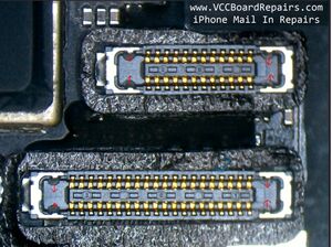
Troubleshooting Steps and Solutions [ edit | edit source ]LCD Connector: [ edit | edit source ]Diode mode the LCD connector (J4502) and check for any shorts (0.000 V) or OL on a line where there should be a reading (≈200–700 mV). Generally, a line labeled with «LCM» is related to image. Think of «LCM» as «LCd iMage». Often times, you’ll find one these lines shorted to ground:
If shorted, you’ll need to inject voltage to find the shorted capacitor. Please note: Inject no more than 5.7 V but it is recommended to inject like 2 V or 3 V and see if that’s enough to find the short. Injecting 5.7 V will inject too much power too quickly and cause the heat to spread really fast and hard to pinpoint the shorted capacitor. Sometimes, you’ll find an OL reading at PP1V8_LCM_CONN. If so, find FL3906 and check for pry damage or blown filter. Replace if you get a diode mode reading on one side of the filter, but OL on the other. Both sides of the filter should give you the same diode mode reading. Chestnut (U3703) — Image IC [ edit | edit source ]If diode mode reading at the LCD connector is good, check Chesnut (U3703), which is responsible for image. Check C3703 for continuity across it. It should not have any. If there is continuity, replace it. Check if there’s any water damage under Chesnut. Lift the IC and see if any corrosion is present. If so, clean corrosion and replace Chesnut and test again. If still no image, diode mode the pads underneath Chestnut and check for any shorts or OL on a line where there should be a reading. If you find a shorted line, track down the shorted capacitor by injecting voltage If you find an OL where there should be a reading, follow the path of the line and diode mode every at every point. Find the point where the diode mode reading reappears. That should be where the line is disconnected and you’ll need to replace the component that disconnected the line, usually a filter. If no abnormal readings under Chestnut, just replace Chestnut and test again. |
| No Touch — Phone turns on but touch doesn’t work | Symptoms:
Troubleshooting Steps and Solutions
|
| Bootlooping — Error 9 | You’ll want to check these first to confirm you have a board issue:
Solution: [ edit | edit source ]If 3uTools Easy Flash gives you a failure at 19% or 20% and 3u Tools iTunes Flash gives you Error 9, then the issue is NAND. You’ll need to replace NAND. NAND is the memory/storage chip. Compatible NANDs [ edit | edit source ]For iPhone 7 and 7 Plus, you can use the NAND of any of the following devices interchangeably:
NAND Programming Process [ edit | edit source ]In order to successfully replace the NAND, you’ll need the following from the original device or NAND and write it to the replacement NAND, otherwise it won’t activate.
It’s also recommended you set these to the correct values, but technically will function fine if you put different values
Tools [ edit | edit source ]You can use any NAND programmer that supports iPhone 7/7P. JC P7 seems to be the most popular. iRepair P10 is another option, that does NAND programming via the lightning port and uses the available «Purple Mode» exploit. What if I don’t have the original NAND data? [ edit | edit source ]You can get the required NAND info from above, by reading the original NAND from the device. In most cases, you should be able to read the NAND data. If it can’t, you’ll need to find it elsewhere
Sometimes, the GSX report service is not available. Using MagicCFG Recovery First, you’ll need to install the replacement NAND, with any generic data filled in for SN, WiFi, BT, etc.. Then restore the phone Then you need to jailbreak the device with Checkra1n After, run the MagicCFG Recovery tool, which will capture the SN, WiFi/BT Mac addresses. Then go back, read the NAND, edit the SN, WiFi, BT addresses and write them again into the NAND Then restore one more time Now you should be able to activate the device. |
| Random Restarting (Usually after 3 minutes) | You’ll want to check these first to confirm you have a board issue:
Symptoms [ edit | edit source ]
If you see any or all of the symptoms above, it is usually a sign the phone cannot «talk» to the battery. TIGRIS_BATTERY_SWI_CONN is responsible for transmitting data from the battery to Tigris to the CPU. Solution [ edit | edit source ]
Final Testing [ edit | edit source ]
|
| Phone will restart when you make a phone call | Symptoms: [ edit | edit source ]When you make a call, the phone will instantly restart or shut off. Testing and Solution: [ edit | edit source ]
Explanation: [ edit | edit source ]Usually this is caused by the ALS or proximity sensors getting some corrosion from liquid damage. It’s easier to just replace the part, but sometimes, you can clean off the corrosion with a toothbrush and isopropyl alcohol and get the flex working again. Symptoms: [ edit | edit source ]
Cause: [ edit | edit source ]
Solutions: [ edit | edit source ]
|
| Home Button will rapid click when you press it | Please Note: iPhone 7 and 7 Plus Home Buttons are paired to the phone, so you cannot replace the home button. If you do, the home button will completely stop functioning. No click and no Touch ID. Only Apple, AASP, and IRP are able to replace home button and get home button function and Touch ID function working. Источник  Введение Технологии развиваются с невероятной скоростью  Введение: Apple является одной из самых известных и  Кастомизация гаджетов Apple – это процесс изменения |